This thread has been locked.

If you have a related question, please click the "Ask a related question" button in the top right corner. The newly created question will be automatically linked to this question.

SN74121: Pulse Extension Issue (Jittering, possible calculation error)

Part Number: SN74121

Hello,

Apologies if I've placed this in the wrong section. 

I'm currently working on a university project to build a pulse extender with the ability to alter the output using a programmable potentiometer board. (RS232 - 8 Channel board from National Control Devices). 

All components apart from the board are being powered using a 5v supply, with the board using a 12v supply. The input pulse is a 5v pulse of 350ns duration. 

My minimum output value is around 515ns output with 10nF and 10Ω on the timing circuit. However when I put the potentiometer up to its maximum value of 50kΩ my output pulse only reaches 60us. By my calculations this should exceed that value all the way up to 300us+. The output signal is also very jittery, going between roughly 58us-63us. My aim is to reach a maximum value of 100us whilst keeping the minimum 515ns intact. 

I've placed a 10Ω resistor in series with the potentiometer as the board does not seem to function unless this is in place. 

Any advice you can give would be appreciated, have I just made a silly calculation error and that is the actual value? Am I missing something else? 

Thanks!

  • Hello Callum,

    How do you have your circuit connected? Can you provide a schematic?
    If we look at Figure 6 in the datasheet with 10nF and 50k, you are correct, it should be close to 300us, so I believe your calculations are likely correct.
    It makes me wonder however if you have a capacitor that is lower than what you believe. Maybe 1nF instead of 10?
    As for the jittery output, the output isn't going to be an exactly precise pulse width every time, there is going to be some variation between the pulses. Figure 1 shows a distribution for the output pulse width based on 101pF and 10kOhm.

    Thank you for joining and coming to the E2E forums! Please continue to post questions here as we are always happy to help.

    Best,
    Michael
  • Hello Michael,

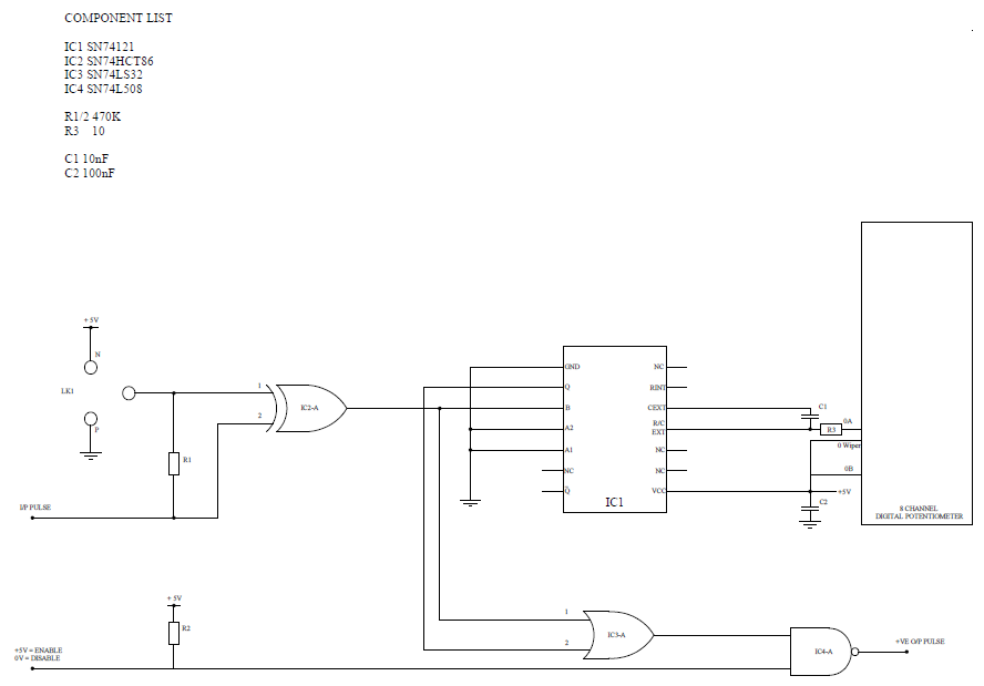
    Thanks for your reply, I shall attach a drawing below. Please excuse the rubbishness, I've been fighting with the software to produce it. 

    So the drawing is based off a previous drawing from my work team as eventually the circuit will be integrated into a larger scale circuit. This is currently a single channel prototype that I've built up on breadboard and tested with a pulse generator and oscilloscope. I've double checked the capacitor and it is definitely the value as stated. 

    As for the jitter, is there a way to smooth that out any further? It seems to be almost non existent at lower levels and progressively gets more jittery as I increase the resistance of the digital pot. 

    Thanks! 

  • Forgot to mention that LK1 is linked to ground currently!
  • Hello Callum,

    Since you are using a digital potentiometer, it makes me wonder if there are some parasitics from the digital pot that are causing issues at the Rext/Cext pin.
    Especially since a resistance between the Rext/Cext pin is required for it to even operate correcty, I wonder if there is some capacitance or other parasitic causing the multivibrator circuit to be inaccurate.
    I would be curious to see what the waveform at the Rext/Cext pin looks like if you can get a scope shot. This pin is the most critical for operation, as the discharging/charging of the Cext capacitor is what triggers the output pulse.
    It would also be interesting to see if you replace the digital potentiometer with a resistor of the intended value to see if it operates differently.
    Is it possible you could do these two things to help me understand better what might be happening?

    Best,
    Michael