This thread has been locked.

If you have a related question, please click the "Ask a related question" button in the top right corner. The newly created question will be automatically linked to this question.

SN74LVC1G04 no input, but got issue

Other Parts Discussed in Thread: SN74LVC1G04

Dear Team:

 Our customer used SN74LVC1G04 and got strange issue as nelow.

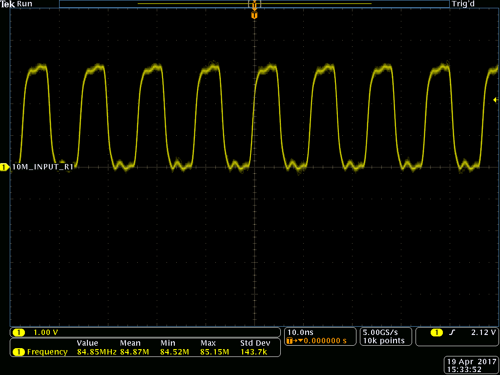
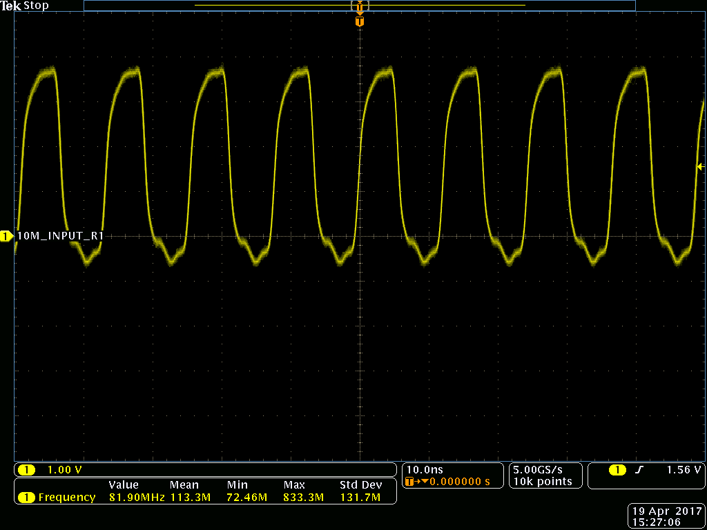
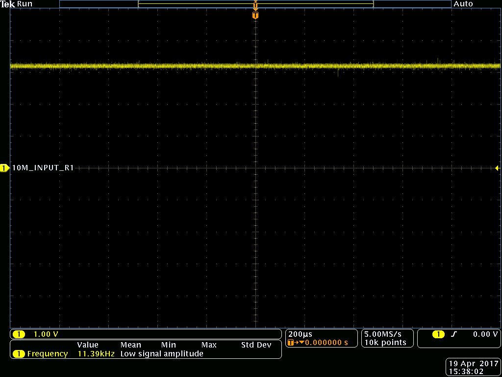
The circuit is asbelow. When there are no input, They got 100MHz at 10MHz_input_R1 and 10MHz_input trace net.

I also asked them to remove some components to measure the waveform again.

1.       Remove C340, and check whether these waveform changed or not.

2.       If no any change, please remove R465, and check whether these waveform changed or not.

3.       If no any change, please remove R464, and check whether these waveform changed or not.

Do you think the 100MHz is really generated by our chip and the circuit?

  1. Remove C340

  2. Remove R464

  3. Remove R465


  • An inverter with negative feedback is an oscillator. However, there is no mechanism whatsoever to control the frequency, so without an input signal, what you get is determined by the actual switching speed of the two inverters, their actual drive strength, and any parasitic capacitances and inductances in the circuit. In other words, without an input signal, the output frequency is random.

    What is the actual problem this circuit is supposed to solve? Should it generate a signal with approximately 10 MHz? Or should it continue to output the last frequency coming from the input?

  • I agree with Clemens. I would say its a bad idea to have the CMOS digital inverter configured as an analog amplifier /oscillator which will bias it in linear region. The trip points are not defined and hence switching cannot be controlled precisely. The 4.7k resistor is small compared to the CMOS high input impedance. A better approach would be to use schmitt trigger as oscillator.