This thread has been locked.

If you have a related question, please click the "Ask a related question" button in the top right corner. The newly created question will be automatically linked to this question.

SN74LVC1T45: Conversion between TTL 5V and LVTTL 3.3V

Part Number: SN74LVC1T45
Other Parts Discussed in Thread: TXS0108E, SN74LVC244A

Hello everyone,

I have some signals that are TTL 5V signals and I want to connect them to the FMC connector of the Kintex 7 Evaluation board (LVTTL 3.3V or LVCMOS 15/18/25/33 available).

I have :

- 3 input pins TTL 5V -> LVTTL/LVCMOS 3.3V
- 3 I/O pins TTL 5V <-> LVTTL/LVCMOS 3.3V

Basically, I need a bidirectional level voltage translator (at least for the three I/O pins) that can convert TTL5V into LVTTL/LVCMOS so I don't overpower the input pins of my Kintex 7 board.

I can't find a solution to do that.

Have you got any suggestions ?

Thanks a lot,

Thibault

  • Do you have a direction signal for the bidirectional signals?

    Do the 5 V signals use TTL or CMOS logic levels?
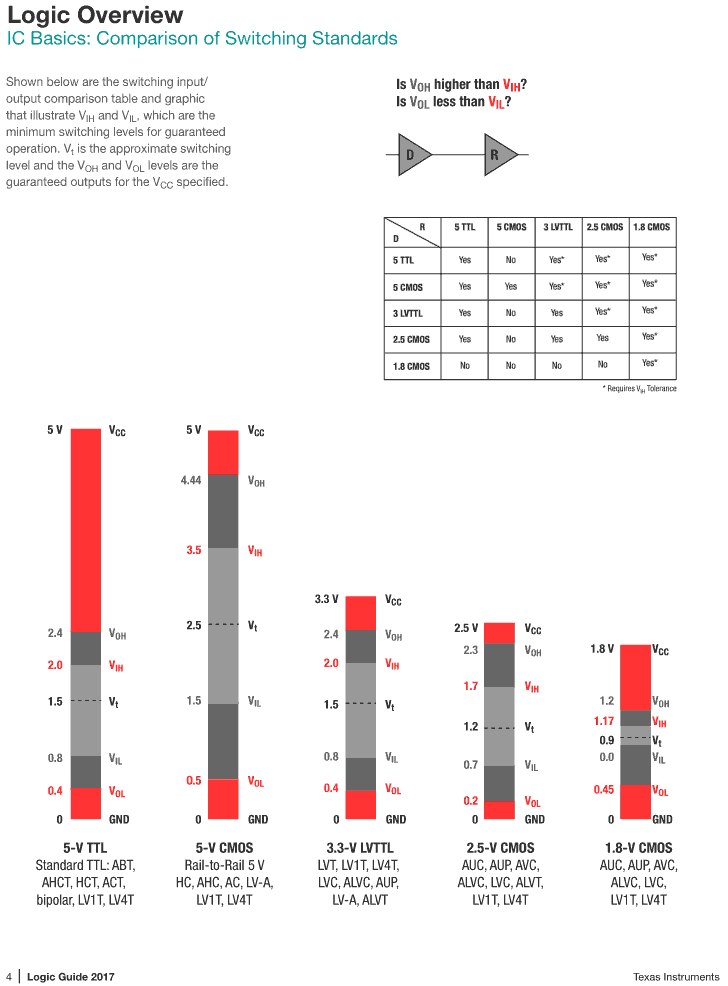
    If they are really TTL, they are mostly compatible with 3.3 V LVTTL; see page 4 of the Logic Guide (SDYU001):

  • Hello,

    I don't have a direction signal for my bidirectionnal signals.

    I don't understand how they can be compatible if TTL is 5V and LVTTL is 3.3V, I need to adapt the voltage between my TTL signals of 5V and my FPGA that is using LVTTL 3.3V ?

    Another question that I wonder is, if I use a component to translate my TTL 5V signals to LVTTL 3.3V, I'm planning to use a cable to transport the LVTTL signal to a second electronic board (kintex 7 evaluation kit). Is there a maximal distance that I should respect for the transport of LVTTL signals ?

    Thanks,

    THibault

  • For a high signal, a chip's output signal is guaranteed to be above VOH, and a chip's input signal is guaranteed to interpret any voltage higher than VIH as high.

    As you can see above, these relationships match for 5 V TTL and 3.3 V LVTTL.

    True TTL outputs do not actually output a 5 V high signal, but something near 3.3 V, so they would not overload a 3.3 V input.

    If your 5 V signals are not TTL but CMOS, you could use something like the TXS0108E.

  • Hi Thibault,

    I think you're using the term "TTL" incorrectly. Most modern systems do not use TTL (Transistor-Transistor Logic, built using Bipolar Junction Transistors, mostly parts developed in the 1960's to the 1980's), but use CMOS logic (Complementary Metal-Oxide Semiconductor, the most common form of logic available today). This is a very common mistake (and one I made before I had this job), and most people just mean "5V logic" when they say "TTL" -- which is why Clemens is trying to clarify.

    A real TTL device won't output 5V if the supply is 5V, it will actually output somewhere closer to 3.3V (many of TI's old TTL devices have a guaranteed "output high" voltage of 2.4V minimum, 3.4V typical). This is how the device was designed, and it's not a very efficient design either -- it just so happens to be how the very first logic devices worked. Today, with CMOS devices, the supply value you put in will be very close to the output voltage you get out.

    The first big question I have is: can your FPGA support input voltages above it's supply value?  It's not uncommon for devices to support inputs with a voltage greater than their supply, and that's something you'd have to find out from the FPGA datasheet (or the FPGA manufacturer). If it can support a 5V input, we're done -- no need for a translator at all!

    If you discover that the FPGA can't support a 5V input, or if you want to err on the side of safety, a translator (probably) won't hurt anything. If your signals are unidirectional (only going from the 5V device to the 3.3V device) , then a simple buffer is the best solution.  Something like the SN74LVC244A could do the trick. There are also auto-bidirectional translators like the TXS0108E that Clemens mentioned, but I would only recommend that if it's really necessary.

    I primarily mention this because you're asking about cable length.  If you have long cables connected to a translator, you can run into problems due to excessive load capacitance - especially with auto-bidirectional devices (they have weak drive strength by design, so large capacitances typically are not supported). If you're talking about a couple of wires running from one board to another, there's probably no issue as long as you're talking about something relatively short (ie what might fit on your typical desk, ~10" of 20ga wire).

    I could probably continue and write a whole book here, but suffice it to say - the more information you give us about what you're trying to do (schematics and images always help, too), the more we can help.

    Please let me know if I can be of further assistance.