This thread has been locked.

If you have a related question, please click the "Ask a related question" button in the top right corner. The newly created question will be automatically linked to this question.

LM567C: Using as a PWM signal generator by modulating pin 2

Part Number: LM567C

I am using the circuit on data sheet page 17 with timing R =1.2k, timing C = .0015, Rload = 1.2k, C2 = .005. Pin 2 floats at approx 3 volts. In order to get an output at pin 8, I have to pull pin 2 down to 230 mV and apply a 100 mV peak to peak signal to get 0 to 100% duty cycle PWM. Is my application correct? 

  • Hi Mervyn,

    Thank you for reporting your findings. I'm not very familiar with this device, but its seems you were able to get this device working as an oscillator. If you need further assistance, I could recommend some debug steps for further investigation.

    Kind regards,
    Lane
  • Using the circuit per figure 18, no contact to pin 3 and AC couple a sine wave to pin 2. I observe frequency modulation at pin 1. Pin 8 remains at a high level. Should I expect more out of this circuit?
  • Pin 2 connects to the VCO, so I would expect applying a DC voltage here to set the VCO frequency. Any input on this pin will be filtered by the loop filter, therefore the sine wave may be attenuated depending on the frequency. I would expect the output on pin 8 to match Figure 19

    Kind regards,
    Lane
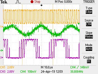
  • I would like to correct my statement about pin 8. It is actually low when pin 2 is unmodulated. This changes to high when pin 2 is 0 volts. At approx. 250mV pin 8 has the waveform per fig 19. If a 100mV sinewave is superimposed, then pin 8 turns into a PWM waveform.

    Question: is the note VCO terminal (+6%) a reference to pin 2 being approx. 300 mV?

    I have attached scope traces of pin 5 yellow, pin 2 green and pin 8 magenta .

    Is this what I have been looking for?

  • You mentioned that "At approx. 250mV pin 8 has the waveform per fig 19", this is the behavior to look for. To confirm, superimposing the sine wave created the PWM on pin 8, but without the sine wave super imposed you observe a normal square wave on pin 8?

    Kind regards,
    Lane
  • It is necessary to deliberately sink current out of pin 2 until pin 8 effectively becomes unstable at around 250 mV. This is somewhat ridiculous and without proper documentation this application is useless.

    I have abandoned this chip in favor of Linear Tech LTC6992.