Other Parts Discussed in Thread: SN74LVC4245A, ALLIGATOR, SN74LVC8T245
Hi there,
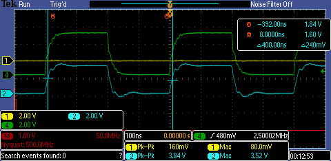
I am currently trying to drive a 2.5 MHz square wave through the TXB0108 device. I believe there is a problem in the matching of the line/termination. The same FPGA with the same configuration is driving a SN74LVC4245A shifter device with reasonable signal integrity. See the following scope screenshot:

The signal through the SN74LVC4245A, PCB trace, and a 50 ohm resistor is shown in blue, and exhibits the expected frequency, peak-to-peak, and maximum values. The signal shown in yellow is being driven through a TXB0108, PCB trace, and 50 ohm resistor. If the signal provided from the Spartan-6 is held high or low, the corresponding TXB0108 output does settle to the correct value (5 V or 0 V respectively).
Furthermore:

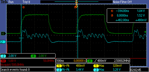
The yellow trace is unchanged, while the blue shows the value measured at the output of the TXB0108 (before the PCB trace and 50 ohm resistor).
Finally:

A measurement taken at the corresponding input to the TXB0108. I think there may be a measurement error here due to parasitic leakage of the measuring probe.
In all cases, the maximum of the yellow line (an output on the 5 V side) is equal to the supply voltage at VCCA (a little over 3.3 V). The output will go to 5 V for a steady high value though.
My question is, given that the TXB0108 and SN74LVC4245A are operating under identical configurations here, why is it that the signal integrity for only the SN74LVC4245A acceptable? Looking at the datasheets, no significant difference is apparent in the specifications. I assume I'm missing something!
Thanks a lot,
Ian