This thread has been locked.

If you have a related question, please click the "Ask a related question" button in the top right corner. The newly created question will be automatically linked to this question.

SN74AVC1T45: May I have some confirming item for SN74AVC1T45 application ?

Part Number: SN74AVC1T45

Dear SIR:

Good day!!
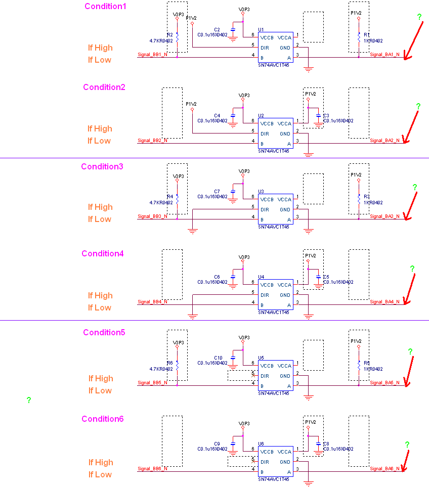
May I have  some question regarding "SN74AVC1T45".

If SN74AVC1T45 pin 6  we have connect to 3.3V Power 

                             pin 5  we NC.

                             pin 2  we have connect to GND

                             pin 4  we have connect to Signal B

                             pin 6  we have connect to 3.3V Power

The "SN74AVC1T45" pin 3 will got any signal ?

(Ex: If Signal B =High  ,How about Pin 3 ? (High or Low or ,...)

        If Signal B =Low  ,How about Pin 3 ? (High or Low or ,...)

)

Thanks

  • Dear sir:

    good day!!

    One more question have any spec. mention  that regarding "SN74AVC1T45" VCCB and VCCA current consumption ?

    Thanks

  • What about pin 1?

    The DIR pin must not be left open; its value might be read as high, or low, or oscillating. See Implications of Slow or Floating CMOS Inputs.

    For how to compute the power consumption, see CMOS Power Consumption and Cpd Calculation.

  • Hi Alex,

    To echo Clemens's post,

    Are you connecting pin 1 to anything?

    Are you connecting pin 5 to anything?

    "The DIR pin must not be left open; its value might be read as high, or low, or oscillating. See Implications of Slow or Floating CMOS Inputs."

    Also, Page 6 of the SN74AVC1T45 datasheet gives the current consumption of supply pins (written as Icca & Iccb).

    Thanks!

    Chad Crosby

  • Dear SIR:

    Good day!!

    Thank for your reply.

    Replay as below:

    Are you connecting pin 1 to anything?==>No, The pin 1 no connect to anything. (N.C.)

    Are you connecting pin 5 to anything?==>No, The pin 1 no connect to anything. (N.C.)

    "The DIR pin must not be left open; its value might be read as high, or low, or oscillating. See Implications of Slow or Floating CMOS Inputs."

    Also, Page 6 of the SN74AVC1T45 datasheet gives the current consumption of supply pins (written as Icca & Iccb).

    ==>Double confirming ,Is that mention  ICCA + ICCB  Max 20 uA  for SN74AVC1T45 total current consumption ?

    Another question :

    SN74AVC1T45 have any "Internal pull High or pull down " or NOT for pin 3 (A)  and Pin4(B) ?

    Because SN74AVC1T45 datasheet page 16 mention "Pullup/Pulldown or Bus Hold†" on pin 3 (A)  and Pin4(B) 

    (1)Is that meaning we need add "external  pull High or pull down " for  pin 3 (A)  and Pin4(B) ? (Normally application)

    (2)Is that meaning we need add "external  pull High or pull down " for  pin 3 (A)  and Pin4(B) ? (below application)

        ================="external  pull High or pull down " for  pin 3 (A)  and Pin4(B)==================

    SN74AVC1T45    pin 6  we have connect to 3.3V Power 

                                 pin 5   NC.(No connect anything)

                                 pin 2  we have connect to GND

                                 pin 4  we have connect to Signal B (External pull 4.7K High 3.3V)

                                 pin 1  N.C (No connect anything)

    The "SN74AVC1T45" pin 3 will got "High(1.2V)" signal ?  (Because   External pull 4.7K High 1.2V))

     ======================================== 

     ================="Without external  pull High or pull down " for  pin 3 (A)  and Pin4(B)==================

    SN74AVC1T45    pin 6  we have connect to 3.3V Power 

                                 pin 5   NC.(No connect anything)

                                 pin 2  we have connect to GND

                                 pin 4  we have connect to Signal B (without External pull 4.7K High 3.3V)

                                 pin 1  N.C (No connect anything)

    The "SN74AVC1T45" pin 3 will got "its value might be read as high, or low, or oscillating" signal ? 

    (Because pin 3 without External pull 4.7K High 1.2V) and Pin 5 (DIR) N.C (No connect anything) )

     ========================================                         

      Thanks

  • Hi Alex,

    Can you post a screenshot of your schematic please?

    Pins 1 & 6 are both supply pins, meaning this:

    When converting from Voltage A --> Voltage B, Pin 1 MUST be connected to voltage A, & Pin 6 MUST be connected to voltage B.

    Additionally, Pin 5 is the Direction Control pin, and it MUST be connected as follows:

    If converting from A -> B : Connect Pin 5 to Voltage A.

    If converting from B -> A : Connect Pin 5 to Ground.

    Pin 5 CANNOT be left disconnected.

    "Double confirming ,Is that mention  ICCA + ICCB  Max 20 uA  for SN74AVC1T45 total current consumption ?"

    Correct, ICCA + ICCB is the maximum total current consumed from both supply pins.

    To answer your other applications, I need to see a schematic.

    Thanks!

    Chad Crosby

  • Dear SIR:

    Upload as attached file.

    Thanks

  • Hi Alex,

    I believe condition 4 is what you're looking for.

    If B ---> A, then option 4.

    If A ---> B, then option 2

    Thanks!

    Chad Crosby

  • Dear SIR:

    Thanks for your reply.

    But,seems didn't resolved my question,May I double confirming that :

    (1)SN74AVC1T45 Pin 4 (B) and Pin3 (A) have internal pull high or low ?

         A---->B:(Because Pin 5 pull High )

           ( Change another word:

            condition 1 Pin 4 (B) and Pin3 (A) with external pull High and Pin1  no connect to P1V2 ; condition 2 without external pull high and Pin1  have connect to P1V2)

            (1-1) If Pin3 (A) didn't  provide signal ,the condition 1 Pin3 (A) will pull high by External resistor R1 ,condition 2 Pin3 (A) will pull high by Internally to Pin1(VCCA ,P1V2),Right?

            (1-2) How about  the Pin 4 (B) result in  condition 1 and  condition 2 ?

                    (Is  condition 1 Pin4 (B) will pull high by External resistor R2 ,condition 2 Pin4 (B) will pull high by Internally to Pin1(VCCB ,P3V3),Right?  )

    (2)condition 5 and condition 6 because Pin 5 didn't pull High or pull down," floating "

         ,therefore sometime will become A---->B  and sometime will become B------>A and sometime will become B <------>A and sometime will become B ----X----A,Right ?       

    Thanks

  • Hi Alex,

    Its hard to follow what you are asking, but I think the confusion here is whether or not the device has internal pull-ups/pull-downs. The answer is no, there are non internal. So if you leave  pins like VCC and direction pins floating then the operation will be unknown. External pull-ups will need to be used to not leave any pin floating. 

  • Dear SIR:

    Thank for your reply,But I more confused.Would you base on below question reply directly ?

    your reply(A):

    I believe condition 4 is what you're looking for.

    If B ---> A, then option 4.

    If A ---> B, then option 2

    your reply (B):

    Its hard to follow what you are asking, but I think the confusion here is whether or not the device has internal pull-ups/pull-downs. The answer is no, there are non internal. So if you leave  pins like VCC and direction pins floating then the operation will be unknown. External pull-ups will need to be used to not leave any pin floating. 

    your reply(A) "option 2 and option 4 " Pin 4 (B) and Pin3 (A)  have no  External pull high and low , different your reply (B) mention that 

    "External pull-ups will need to be used to not leave any pin floating."

    Therefore:

    (Q1)The Pin 4 (B) and Pin3 (A) external pull high /low necessary or not ?

    (Q2)As your reply the Pin 4 (B) and Pin3 (A) have no internal pull high /low ,base on pin function mention "Input/output A. Referenced to VCCA"

           "Input/output B. Referenced to VCCB" ,What's the meaning regarding ""..............Referenced to VCCA"" ,".............Referenced to VCCB" ?

    (Q3)

    (Q3-1)For condition 1 

         Pin 4 (B) and Pin3 (A) with external pull High and Pin1  no connect to P1V2 ; condition 2 without external pull high and Pin1  have connect to P1V2)

            (Qa-1) If Pin3 (A) didn't  provide signal ,the "condition 1 and condition 3 "Pin3 (A) will pull high by External resistor R1 ,Right?

                        Because Pin1  no connect to P1V2 ,Therefore condition 1 dis-connected between Pin3 (A) and Pin4 (B) ,Right?

                        If Pin3 (A) didn't  provide signal ,the  "condition 2 and condition 4 " Pin3 (A) and Pin4 (B) will "floating",but ,connected between Pin3 (A) and Pin4 (B) ,Right?

     (Q3-2)condition 5 and condition 6 because Pin 5 didn't pull High or pull down," floating "

         ,therefore sometime will become A---->B  and sometime will become B------>A and sometime will become B <------>A and sometime will become B ----X----A,Right ?       

    (Q4)

    Is  it  mention regarding SN74AVC1T45   Pin1(VCCA) or  Pin6 (VCCB) either one no connect to VCCA or VCCB (Floating ) ,It will dis-connect between Pin3 (A) and Pin4 (B) ,Right ?

    (Because ,Pin1(VCCA) ,  Pin6 (VCCB) are A port ,B Port internal logic supply power ,

                     Pin1(VCCA) =floating ,meaning  port A  internal logic no work ,therefore ,,It will dis-connect between Pin3 (A) and Pin4 (B)  

                     Pin6(VCCB) =floating ,meaning  port B  internal logic no work ,therefore ,,It will dis-connect between Pin3 (A) and Pin4 (B) ,too. )

    (or I have any mis-understanding ?)

    Thanks

  • Dear SIR:

    Would you have any update ?

    Thanks

  • Hi Alex,

    (Q1) If Pin 4 & Pin 3 are not connected to anything, they must be pulled up. See below:

    (Q2) When converting from B --> A or A ---> B, Voltage A = Vcca and Voltage B = Vccb. 

    (Q3) 

    Condition 1

    Wrong: Pin 1 is not connected to P1V2

    Condition 2

    Correct, A --> B. Pin 1 MUST be connected to P1V2.

    If Signal_BB2_N is connected to another circuit, resistor is not needed.

    If Signal_BA2_N is connected to another circuit, resistor is not needed.

    If either are NOT connected, resistor is needed.

    Condition 3

    Wrong: Pin 1 is not connected to P1V2

    Condition 4

    Correct, B --> A. Pin 1 MUST be connected to P1V2.

    If Signal_BB2_N is connected to another circuit, resistor is not needed.

    If Signal_BA2_N is connected to another circuit, resistor is not needed.

    If either are NOT connected, resistor is needed.

    Condition 5

    Wrong: Pin 1 is not connected to P1V2, Pin 5 is not connected.

    Condition 6

    Wrong: Pin 5 is not connected.

    (Q4) If Pin 1 or Pin 6 are floating (not connected to anything), it does not mean that the circuit is disconnected. See:

    Thanks!

    Chad Crosby