This thread has been locked.

If you have a related question, please click the "Ask a related question" button in the top right corner. The newly created question will be automatically linked to this question.

SN74AHC05: Part catches fire during noise test...

Part Number: SN74AHC05

Specific Device PN: SN74AHC05PWR

Customer was performing some over-stress noise tests, (see following) and the device ignited into flames at the following conditions:

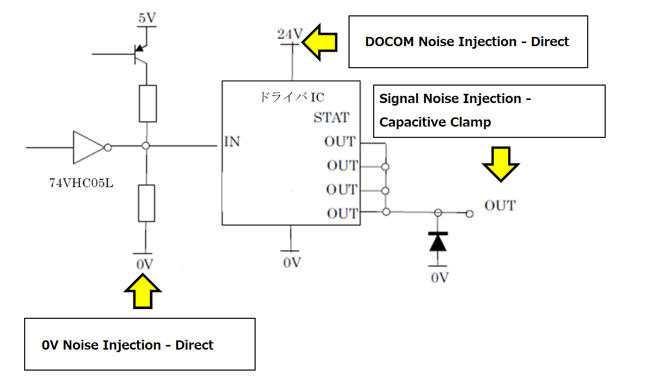
Test 1: Noise applied to the signal line(OUT) of greater than +2.4kV or less than -4kV caused ignition and fire(capacitive clamp)

Test 2: Noise applied to the DOCOM(24V) line of greater than 1.6kV and under -1kV caused ignition and fire (direct)

Test 3: Noise applied to GND (0V reference potential for device) of >+1.8kV or <-2.0kV caused ignition and fire (direct)

For Test 3, the kV-rating where ignition and fire happened varied with the location on where the 0V line noise was injected.

Because these were over-stress conditions, they know nothing is wrong with the TI device functionality. But they would very much like to avoid failures with ignition and fire. Are there any design considerations or steps than can be taken to mitigate fire during device failure?

Also, they very much hope we can provide them the mechanism on how such a failure could occur. At such high noise voltage (not sure how long the pulses were...), is it the bonding wires melting and igniting the package that cause such a failure? What is the flame-retarded rating of the packaging material...?

Regards,

Darren 

  • Hi Darren,

    It's hard to follow the test description without seeing what you are seeing. Though, there isn't really any preventative measures to account for operating the device this far outside of the recommended spec range. The best way is to avoid it by adding preventative measures in the system. Excessive current is typically the mechanism for heat generation.

  • I have attached a brief outline below.

    Best method is current limiting techniques...because current = heat = fire...understood, thanks.

    But is there any information on the flammability of the package material? I mean, instead of melting or just smoking it actually caught fire...

    Is there an epoxy you could put over the package to keep fire from happening?

    Do you have a rough idea of a slightly more "detailed" mechanism for such a failure? Even just your opinion given the below outline...

    I mean, the noise wasn't actually applied directly to the SN74AHC05...☟

  • Hi Darren,

    If you're interested to see what exactly a device is made of, you can use the following page: http://www.ti.com/materialcontent/home

    As for preventing a fire from happening, this device is rated for operation at a maximum supply and maximum inputs of 7V. Supplying this device, or using inputs in the kV range is a sure way of causing a fire, and I'd recommend changing the supply voltage before any other steps are taken.

    Thanks!

    Chad Crosby

  • Hi Chad,

    That link for material content is great. Really, that you for sharing that nugget of wisdom :)

    As for the noise...I understand it isn't ideal, but I believe this was a standard ESD/EFT/Surge noise test, and the test was applied at the VDD(24V)  and output of another device (a driver IC), and this device didn't burst into flames...instead, whatever happened propagated through that driver IC, and through the SN74AHC05PWR, which was the only device to catch fire. Usually devices don't catch fire during ESD/EFT/Surge testing...

    EDIT: Could you confirm that the output of setup from the attached image in my previous post? That is, a PNP transistor pulling up to 5V, then a resistor divider? Do you see any "problem" with that setup connecting to the input of a driver IC?

    I will share the material package links with the customer, and let them try and see if they can understand what happened based on their testing, and the package parameters. (Unless you have anything else? For now, I will mark the above as resolving the issue)

    Darren

    http://www.ti.com/materialcontent/en/report?pcid=43927&opn=SN74AHC05PWR

  • Hi Darren,

    No, I see no issue with the BJT + Resistor divider circuit you have. The only issue that is causing a fire to start here is the extremely high voltages being input to the SN74AHC05 device. At a certain voltage, well outside the specification given in the datasheet for this device, the silicon oxide between the gate and body of the internal mosFET breaks down and essentially shorts. This means that the device no longer acts like an inverter, but rather a resistor.

    If your customer is expecting to see these extremely high voltages due to ESD or EFTs, they'll need to provide some additional protection circuitry around our device. TI only guarantees operation of the device within the specification listed in the datasheet, which is 7V.

    Thanks!

    Chad Crosby 

  • Hi Chad,

    I really appreciate you helping out with this.

    You mention additional protection circuitry...would you recommend adding a pulse-proof resistor (usually done with RS-485 devices) to the output of the inverter? Something around 10 to 20 ohms? (This is one way to help limit the inrush current from the ESD / Surge event...?)

    Any other "additional protection circuitry" you might recommend? Like a TVS diode?

    Regards,

    Darren