This thread has been locked.

If you have a related question, please click the "Ask a related question" button in the top right corner. The newly created question will be automatically linked to this question.

CC2541 Service discovery in power saving mode

Other Parts Discussed in Thread: CC2541

In both the SimpleBLEPeripheral sample program and HostTestRelease, when I enable power saving using the POWER_SAVING preprocessor symbol, I am unable to discover services. The device is still discoverable, but when I attempt to connect my test app just disconnects immediately instead of finding the services and characteristics. Does anyone have experience with this? Maybe I have to wake the processor up?

  • Hi Christopher,

    What's the board you are running your code on? Do you have a sleep crystal mounted? This is required to stay in a connection.

    It seems like either a) the sleep timer frequency is wrong, or b) the 32MHz crystal is slow to start up.

    BR,
    Aslak

  • Hi Aslak, thank you for the response. We are using a network configuration using an MSP430 and the CC2541. For our clock, we have an oscillator for the 32MHz clock on the MSP430, and this clock is being sourced from pin 1 to the CC2541 32MHz clock. So in other words, the CC2541 is using the clock from the MSP430, it does not have its own oscillator/crystal.

    -Chris

  • I tried a couple of tests, and I believe it does have something to do with the 32 KHz clock. When I run the simple peripheral sample program on a Tiwi-ub1 eval board with power savings it works fine. When I run the same program on the prototype board where the MSP430 is supplying the 32 KHz clock, this problem happens. Do I have to turn the clock off when it is in low power mode?

  • Have you tried setting the bit OSC32K of the CLKCONCMD to 0?

    Power saving doesn't seem to work when using the internal 32 kHz RCOSC.

  • The stack will write to the CLKCONCMD register to switch to external crystal.

    Have you followed the appliation note on this and ensured the clock is ticking at the correct frequency and connected to Q2 on the crystal pins?

    http://www.ti.com/lit/an/swra409/swra409.pdf

    Regards,
    Svend

  • Svend, 

    We have designed it according to this application note, except the other pin on the oscillator is not connected to ground (it is open). However, I removed the capacitor connected to this pin on the eval kit and it worked fine, and tech support from LS research said this would not be a problem.

    One other hardware difference we have from the eval board is that we removed the 2.1V regulator so that the CC2541 runs on 3.3V instead of 2.1. Is there maybe some configuration in the code that needs to be changed because of this?

  • There is a bit macro for a GPIO called DCDC_SBIT which will set P0.7 high/low to turn the DC/DC on/off.

    This can probably be removed, but shouldn't cause what you are seeing.

    Does your board work fine when POWER_SAVING is not defined as a compiler option?If so I agree, it seems like the 32kHz supplied externally is causing an issue somehow.

    Regards,
    Svend

  • Yes, the board works as expected when POWER_SAVING is not defined. However, I tried supplying the prototype with a 32K clock from a launchpad, which worked fine with the tiwi ub1 eval kit, and still had the same problem.

    I have some more information on the problem. The tiwi ub1 eval kit has jumpers to bypass the 2.1V regulator. When the regulator is bypassed, I have this same problem with not being able to connect and discover the services. When it is not bypassed, it works fine with POWER_SAVING defined. This leads me to believe that the problem is somehow related to not having the regulator.

    What file can I find the macro that defines DCDC_SBIT? I was unable to find it.

    Thanks,

    Chris

  • The DC/DC control using DCDC_SBIT is defined only for the SensorTag code as that is the only TI target that has a DC/DC onboard.

    You can find the definition in BLE-CC254x-1.4.0\Components\hal\target\CC2541ST\hal_board_cfg.h

    Which software project are you currently flashing onto your board and the tiwi ub1?

    If you are using the SimpleBLEPeripheral project as a starting point then there is no DC/DC control enabled so this shouldn't be the cause of any issues.

    Regards,
    Svend

  • That's right, we are using SimpleBLEPeripheral as a starting point and plan on using Hosttestrelease. So it seems like this should have nothing to do with the DC/DC, but it is weird that I see the same exact issue on the eval board when the regulator is bypassed.

    Another small piece of info: sometimes when the app tries to connect, typically the first time after a reset, I receive an "Unknown error".

  • So when using the LSR module I assume you set the jumpers JMP1 and JMP2 to position 1-2, is that right?

    Why the LSR module doesn't work properly when doing this is hard to say. Several components such as the 32 MHz crystal is probably hidden within the module itself.

    Would you be able to share a schematic with us of your solution?

    BR,
    Svend

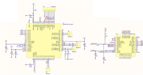
  • That's right, both jumpers were in position 1-2. I've attached the schematic, it is pretty simple. There are some breakout pins not shown, but this is everything relevant.

    There's one more thing I thought of. There are four UART lines connected to the tiwi-ub1 which will be used in the actual solution. They are not used in SimpleBLEPeripheral example however, so I wonder if they are interfering in some way.