This thread has been locked.

If you have a related question, please click the "Ask a related question" button in the top right corner. The newly created question will be automatically linked to this question.

TRF7960A Tag response decreases extremely

Other Parts Discussed in Thread: TRF7960A

Hi

Our customer is using TRF7960A in their RFID application and currently
they are trying to measure the response from the Tag (Subcarrier 424KHz) using an
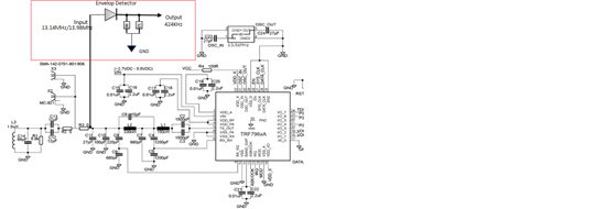
Envelope Detector circuit as shown below. The circuit is as per TI's reference design.
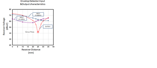
The issue is the that at some point the response decreases extremely.

As shown in the below graph the response is decreased extremely at 25mm distance.

We are not able to understand the reason behind this issue.
Please let us know if there are any suggestions.

Regards
Prad

  • Prad - 

    is there a reason they are doing it this way versus using built in RSSI feature of the device? 

    Also, usually - when making a complete envelope detector, the diode would also be accompanied by a filter...perhaps like this: 

    or this: 

    any more details on the setup, the antennas (tag and reader) which tag IC, etc.) would be helpful, too. 

  • also, check out: 

    http://www.ti.com/lit/an/sloa184/sloa184.pdf 

    page 25

  • Hi Josh,

    Thank you so much for the quick reply.

    The customer is using RSSI feature also.
    Just in case we would like to know if there are any possibility
    of holes in the TAG response as mentioned above.
    We would like to know if this is a common issue and what could be
    the reason behind this hole.

    Regarding more details on the setup, antennas (tag and reader) etc
    it may be difficult to post the details here. Is it possible to send you
    the details through mail? my ID is pradeep_kumar@ktl-corp.co.jp

    Best Regards
    Prad

  • Prad - 

    the dual RX'ers on the part are there to eliminate read holes and are delayed electrically from each other by the matching circuit attached externally for that very reason. 

    you can send me direct email with your details, no problem: josh.wyatt@ti.com

  • Prad1, Hello. I have my own answer to the presence of the “NOTCH/NULL/ HOLE”…Sorry I cannot do it justice in three or four cryptic lines; so more later …if you want… some shortcuts first.

    I believe the HOLE (TI Terminology) is due to Bifurcation of two approaching inductively (magnetic coupled) resonant circuits.

    This Bifurcation of the Frequency Response creates TWO low impedance “energy sink-holes” (a pair of series resonant Frequencies equal and either side of the dominant Resonance Frequency, 13.56MHz).

    As the coefficient of Magnetic Coupling (k) changes from Zero(0) to One(nearly 1)… then the coupled NULLS  in the receptor circuit which begin as a single entity,  now progressively form into a matched pair of NULLS either side of resonance and proceed to pan/flare further away as the (k) factor increases.

    In your case I propose that at 25cm separation the (k) factor that exists there is a just right to place one null over 13.56+424KHz and the other mirror image/bifurcated null over the other modulation sideband 13.56-424KHz…

    BOTH SIDEBAND ENERGIES IN THE RECEPTOR CIRCUIT ARE NOW “CONSUMED/DISSIPATED”… AND THEREIN LAYS THE REASON FOR YOUR “DEMODULATED SIGNAL” NULL OR HOLE. (or so I propose).

     This is classic behaviour and you can analogize it with SPICE Analysis, or measure it with a Spectrum- Analyser with Tracking generator… or you can see it’s manifestation by graphing, as you client has done. His “HOLE” appears at 25cm for a given RFID Tag.

    By way of testing my explanation you should ahead of time, ask your clients to do the following for me.

    1. Confirm the Hole remains stationary for 424/212/106KHz modulation.
    2. Confirm a smaller Tag has a “HOLE” closer in than 25cm … always faced forward.
    3. Confirm the “new little” Hole too remains stationary for 212KHz modulation.
    4. Confirm ANY Hole remains in the same place for ANY modulation frequency or Depth.
    5. Confirm a larger Tag has a hole consistently further away than 25cm, and all the above.
    6.  Confirm the “Depth of the HOLE” deepens with higher Q factor of Reader Coil (R1=12K new).
    7. Confirm simultaneous present Big and Small Tags create TWO “NULLS”.
    8. Contemplate Crude Data Collision mitigation based on size and position.
    9. Review/find  the REAL reason and use of the second Receiver input… FM demodulation?

    The first Resonant Circuit is the Reader-Coil (1.5uH) plus the resolution of ALL the components behind it all the way back to the TRF79xxx … Resonant Frequency=13.56Mhz ,(Q~10 ufn).  The Second is my simple L=0.95uH, C=145pF,  Rp=6800  Q~10.

    This below is a fragment of my Spice Frequency Sweep Analysis where I also Step the (k) factor to mimic approaching the Tag to your Reader,  etc  etc.

    If there is validity in my claim I think I can see how to help you with this issue (maybe).

    Kind Regards

    Ray

  • Hi Josh,

    Thank you.
    I shall come back with the details.


    Hi Ray,

    Thank you very much for your time and the detailed information.
    I will check this the customer and let you know the details.
    We appreciate your kind support.

    Regards
    Prad

  • Pard1,  there is one stipulation I propose for you, to consistently  “see” these HOLES … the TagCoil resonance must be EXACTLY the same as the ReaderCoil Resonance… In fact, we know that as the Tags are “free running/tuning” resonators driven by a ”plucking” sample of the Source/Reader oscillation frequency, we have a mixture of fixed and indeterminate variable resonances at work here… it is a mixture of clarity and chaos. Still, you can overcome… To RFID read the garment size of that dress for the wife?

    Then “best- HOLE” manufacture demands both Coil resonances to be identical. In fact there are there THREE Resonances to be considered here: The first is the Crystal Oscillator frequency, the second is the resonance of the Transmitter Coil and the third is the Resonance of the Transponder Coil. Let us not go there just yet, as most often all three will rarely be identical (but sometimes close.)

    How lucky for the client that he found a Tag that developed a HOLE. Ask him can he do it twice or more? Or more likely, does he find more shallow HOLES than DEEP HOLES, and sometimes none at all from the same batch of RFID Tags.

    In the real world, this will be a rare event due to Tag packaging etc … so ahead of time I suggest you will not always “see” a good HOLE as has your client… indeed they are like Sprites they come and go and are delicate.

    As the user cannot see any HOLES, or indeed never gave any thought to their being or could not even care less about them … then all he does is keep advancing his RFID card closer and closer until the “bell rings” or money falls out of his EPTPOS… whether this happens before or after passing OVER a HOLE is ... is well …LUCKY…. And I do mean LUCKY for TI.

    Prad1, my proposition pivots/relates to the “STRANGE front-end network” … I view it as a four port hybrid-combiner… It has two inputs (the Aerial + the Chip Transmit) and two outputs (Receiver1 input +Receiver2 Input) … look closely and you will recognize it… it is an amazing beautiful design… it tries to be all things to all known modes… but in its attempt at diversity, it is its own worst enemy. (Just my opinion).

    Have you not/ever pondered the need for or indeed the true function of the Front-End MULTIPLEXER?...sure, it swaps RX1 with RX2 “on command/software”… and it is true, that this swap is recommended be done on the detection of a “HOLE”? … why? … It WILL ...WILL …  will, give you a new viewpoint that does not include the offending hole behaviour… (I think this whole swapping business was a beautiful accident, that just worked…well done the original designer wherever you are)

    Just Killing time over Easter

    Regards

    Ray

  • Hi Ray,

    Thank you so much for the details,
    and I am sorry for the delay.

    Currently are analysing the details provided.

    If possible could you please provide us more details about this comment.
    "BOTH SIDEBAND ENERGIES IN THE RECEPTOR CIRCUIT ARE NOW “CONSUMED/DISSIPATED”… AND THEREIN LAYS THE REASON FOR YOUR “DEMODULATED SIGNAL” NULL OR HOLE. (or so I propose)."
    -> Is this because of the phase difference on the both side?

    Best Regards.
    Prad

  • Prad1 … why did you delete/remove the valuable cardinal graph which clearly depicts “a hole” as labouredly plotted by your client?  … ( it does take a conscious effort to edit an original post? No accident is involved) … This thread which you started …  “to seek ,some or any” explanation for this (unexpected?)  behaviour;  will now be read by others members as some trite nonsense ramble, by a well-meaning forum member… even yet my explanation is only  cursory and in haste for you, I see some poor wording etc . I too am receptive to corrections, without subliminal technical mockery.

    Ray