This thread has been locked.

If you have a related question, please click the "Ask a related question" button in the top right corner. The newly created question will be automatically linked to this question.

Problems reading register from sensor conected to I2C, using F28335

Other Parts Discussed in Thread: CONTROLSUITE

Hi, I have problems reading the contents of the registers from a sensor conected to the I2C bus in the C2000 Peripheral Explorer Kit. The sensor is the ADXL345, an accelerometer that stores the readings in 8-bit registers (2 registers per reading, one with higher byte and the other with lower byte). The configuration of the sensor should be correct because the debugger goes on step by step.

The program works, but the values read make no sense, because I am obtaining always the same value from those registers, no matter which register I am reading or the position of the sensor. Please find attached the code, I really don't know what is it that I'm doing wrong.

Also, is there anyway to monitor the state of the signals SCL and SDA to understand better if something is being done wrong?

Thank you very much.

//###########################################################################
//
// FILE:	ADXL345.c
//
// TITLE:	DSP28335 I2C test
//          Accelerometer ADXL345 connected to GPIO33 (SCL) and GPIO32(SDA)
//			LED LD1 as life indicator 100 ms toggle
//
//###########################################################################

#include "DSP2833x_Device.h"

// Define register addresses
#define ACCEL 0x53			// slave address
#define ACCEL_WRITE 0xA6	// slave address for writing
#define ACCEL_READ 0xA7		// slave address for reading
#define POWER_CTL 0x2D		// POWER_CTL register at sensor
#define DATAX0 0x32			// LS byte for X measurement
#define DATAX1 0x33			// MS byte for X measurement
#define DATAY0 0x34			// LS byte for Y measurement
#define DATAY1 0x35			// MS byte for Y measurement
#define DATAZ0 0x36			// LS byte for Z measurement
#define DATAZ1 0x37			// MS byte for Z measurement

// external function prototypes
extern void InitSysCtrl(void);
extern void InitPieCtrl(void);
extern void InitPieVectTable(void);

// Prototype statements for functions found within this file.
void Gpio_select(void);
void I2CA_Init(void);

int xaccel = 0;
int yaccel;
int zaccel;

//###########################################################################
//						main code
//###########################################################################
void main(void)
{

	InitSysCtrl();	// Basic Core Init from DSP2833x_SysCtrl.c

	EALLOW;
   	SysCtrlRegs.WDCR= 0x00AF;	// Re-enable the watchdog
   	EDIS;			// 0x00AF  to NOT disable the Watchdog, Prescaler = 64

	DINT;				// Disable all interrupts

	Gpio_select();

	//	Initialize I2C
	I2CA_Init();

	// Initialize and configure ADXL345
	I2caRegs.I2CCNT = 3;					//Send 3 bytes
	I2caRegs.I2CDXR = ACCEL_WRITE;			//Select POWER_CTL register in sensor
	I2caRegs.I2CMDR.all = 0x6E20;			//Generate start and stop, master transmitter
	while(I2caRegs.I2CSTR.bit.XRDY == 0);	// wait until first byte is out
	I2caRegs.I2CDXR = POWER_CTL;			//Select POWER_CTL register in sensor
	while(I2caRegs.I2CSTR.bit.XRDY == 0);	// wait until second byte is out
	I2caRegs.I2CDXR = 0x08;					//Activate measurement mode in sensor
	while(I2caRegs.I2CSTR.bit.SCD == 0);	// wait for STOP condition
	I2caRegs.I2CSTR.bit.SCD = 1;

	InitPieCtrl();		// basic setup of PIE table; from DSP2833x_PieCtrl.c
	InitPieVectTable();	// default ISR's in PIE

	InitCpuTimers();	// basic setup CPU Timer0, 1 and 2

	PieCtrlRegs.PIEIER1.bit.INTx7 = 1;

	IER |=1;

	EINT;
	ERTM;

	EALLOW;
	SysCtrlRegs.WDKEY = 0x55;	// service WD #1
	EDIS;

	//Read acceleration on X axis
	//Higher 8 bits (DATAX1 register)
	I2caRegs.I2CCNT	= 2;					//Write 1 byte (register address)
	I2caRegs.I2CDXR = ACCEL_WRITE;			//Select higher byte register in sensor
	I2caRegs.I2CMDR.all = 0x6E20;			//Generate start and stop, master transmitter
	while(I2caRegs.I2CSTR.bit.XRDY == 0);	// wait until first byte is out
	I2caRegs.I2CDXR = DATAX1;				//Select higher byte register in sensor
	while(I2caRegs.I2CSTR.bit.SCD == 0);	// wait for STOP condition
	I2caRegs.I2CSTR.bit.SCD = 1;

	I2caRegs.I2CCNT	= 1;					//Write 1 byte (register address)
	I2caRegs.I2CDXR = ACCEL_READ;			//Select higher byte register in sensor
	I2caRegs.I2CMDR.all = 0x6620;			//Generate start but not stop, master transmitter
	while(I2caRegs.I2CSTR.bit.XRDY == 0);	// wait until first byte is out

	while(I2caRegs.I2CSTR.bit.ARDY == 0);	// wait for access ready condition
	I2caRegs.I2CCNT	= 1;					//Read 1 byte (register address)
	I2caRegs.I2CMDR.all = 0xEC20;			//Generate stop but not start, master receiver, generate NACK
	while(I2caRegs.I2CSTR.bit.RRDY == 0);	// wait for byte
	xaccel = I2caRegs.I2CDRR<<8;			// read upper 8 Bit (integers)

	//Lower 8 bits (DATAX0 register)
	I2caRegs.I2CCNT	= 2;					//Write 1 byte (register address)
	I2caRegs.I2CDXR = ACCEL_WRITE;			//Select higher byte register in sensor
	I2caRegs.I2CMDR.all = 0x6E20;			//Generate start and stop, master transmitter
	while(I2caRegs.I2CSTR.bit.XRDY == 0);	// wait until first byte is out
	I2caRegs.I2CDXR = DATAX0;				//Select higher byte register in sensor
	while(I2caRegs.I2CSTR.bit.SCD == 0);	// wait for STOP condition
	I2caRegs.I2CSTR.bit.SCD = 1;

	I2caRegs.I2CCNT	= 1;					//Write 1 byte (register address)
	I2caRegs.I2CDXR = ACCEL_READ;			//Select higher byte register in sensor
	I2caRegs.I2CMDR.all = 0x6620;			//Generate start but not stop, master transmitter
	while(I2caRegs.I2CSTR.bit.XRDY == 0);	// wait until first byte is out

	while(I2caRegs.I2CSTR.bit.ARDY == 0);	// wait for access ready condition
	I2caRegs.I2CCNT	= 1;					//Read 1 byte (register address)
	I2caRegs.I2CMDR.all = 0xEC20;			//Generate stop but not start, master receiver, generate NACK
	while(I2caRegs.I2CSTR.bit.RRDY == 0);	// wait for byte
	xaccel += I2caRegs.I2CDRR;				// read lower 8 Bit (integers)

	EALLOW;
	SysCtrlRegs.WDKEY = 0xAA;	// service WD #2
	EDIS;

}

void Gpio_select(void)
{
	EALLOW;
	GpioCtrlRegs.GPAMUX1.all = 0;			// GPIO15 ... GPIO0 = General Puropse I/O
	GpioCtrlRegs.GPAMUX2.all = 0;			// GPIO31 ... GPIO16 = General Purpose I/O

	GpioCtrlRegs.GPBMUX1.all = 0;			// GPIO47 ... GPIO32 = General Purpose I/O
	GpioCtrlRegs.GPBMUX1.bit.GPIO32 = 1;	// GPIO32 = I2C - SDA
	GpioCtrlRegs.GPBMUX1.bit.GPIO33 = 1;	// GPIO33 = I2C - SCL

	GpioCtrlRegs.GPBPUD.bit.GPIO32 = 0;    // Enable pull-up for GPIO32 (SDAA)
	GpioCtrlRegs.GPBPUD.bit.GPIO33 = 0;	   // Enable pull-up for GPIO33 (SCLA)

	GpioCtrlRegs.GPBQSEL1.bit.GPIO32 = 3;  		// Asynch input GPIO32 (SDAA)
	GpioCtrlRegs.GPBQSEL1.bit.GPIO33 = 3;	// Asynch input GPIO33 (SCLA)

	GpioCtrlRegs.GPBMUX2.all = 0;			// GPIO63 ... GPIO48 = General Purpose I/O

	GpioCtrlRegs.GPCMUX1.all = 0;			// GPIO79 ... GPIO64 = General Purpose I/O
	GpioCtrlRegs.GPCMUX2.all = 0;			// GPIO87 ... GPIO80 = General Purpose I/O


	GpioCtrlRegs.GPADIR.all = 0;			// GPIO0 to 31 as inputs
	GpioCtrlRegs.GPADIR.bit.GPIO9 = 1;		// GPIO9 = LED LD1
	GpioCtrlRegs.GPADIR.bit.GPIO11 = 1;		// GpIO11 = LED LD2

	GpioCtrlRegs.GPBDIR.all = 0;			// GPIO63-32 as inputs
	GpioCtrlRegs.GPBDIR.bit.GPIO34 = 1;		// peripheral explorer: LED LD3 at GPIO34
	GpioCtrlRegs.GPBDIR.bit.GPIO49 = 1; 	// peripheral explorer: LED LD4 at GPIO49

	GpioCtrlRegs.GPCDIR.all = 0;			// GPIO87-64 as inputs
	EDIS;
}

void I2CA_Init(void)
{

	I2caRegs.I2CMDR.bit.IRS = 0;	// Reset the I2C module
	I2caRegs.I2CSAR = ACCEL;			//Select write address for sensor
	// I2C Prescale Register
	I2caRegs.I2CPSC.all = 14;		// Internal I2C module clock = SYSCLK/(PSC +1)
								    // = 10 MHz

//	I2caRegs.I2CCLKL = 95;			// Tmaster = (PSC +1)[ICCL + 5 + ICCH + 5] / 150MHz
//	I2caRegs.I2CCLKH = 95;			// Tmaster =  15 [ICCL + ICCH + 10] / 150 MHz
									// d = 5  for IPSC >1

									// for I2C 50 kHz:
									// Tmaster = 20 µs * 150 MHz / 15 = 200 = (ICCL + ICCH +10)
									// ICCL + ICCH = 190
									// ICCL = ICH = 190/2 = 95

	I2caRegs.I2CCLKL = 45;
	I2caRegs.I2CCLKH = 45;			// for I2C 100 kHz:
									// Tmaster = 10 µs *150 MHz / 15 = 100 = (ICCL + ICCH + 10)
									// ICCL + ICCH = 90
									// ICCL = ICH = 90/2 = 45

	I2caRegs.I2CMDR.bit.IRS = 1;	// Take I2C out of reset
}

//===========================================================================
// End of SourceCode.
//===========================================================================
  • Hi,

    Aren't you able to observe anything on the watch window?

    Regards,

    Gautam

  • Hi!! Did you solve your problem? I'm doing the same and I don't know what can I do. 

    Regards! 

  • HI Fernan Aguilar

    I also use i2c to catch some data, but doesn't work. The code it have some problem that i can't figure out.

    Could you do me a favor, provide the example my e-mail:   flyinloving@gmail.com

  • hi: guys

    I find you address of device is wrong .it shoud be 0x0050; I2C slave address struct not allow its datasheet say.

    and first memory address will fill in 0x005x, it is high address. the low address is another memory address.

    so ,TI  I2C address include 1: slave address 0x0050. 2 memory high address in slave address 3:memory low address.

    their are two type together!

    and R/W bit in I2CMDR.bit.TRX. it will automatic add in address. not is data byte.

    you can refer contorsuit some 28335's i2c-eeprome.  that programe is fine.

    best regard!

    yanzheng fu

  • hi yanzhen fu

    i think you don't understand the example of 28335's i2c-eeprom.  

    1. you say the slave address shoud be 0x0050 but in ADXL345 it's 0x53!!  

     2. you say R/W bit in I2CMDR.bit.TRX. it will automatic add in address. not is data byte.=>

    i have checked the example many times!! i can't found where is the "automatic add" \

    if you found it just told me plz!!

  • HI: huang:

    Is 28335 different with 28035's I2C .?  if same, that 0x53 should be wrong .that "3" in high memory address. because I2C slave adree cann't send "3" in slave adree.!

  • Hi huang : can you send  ADXL345 datasheet on post. I want watch it.

  • HI yanzhen fu

    FYI

    http://www.analog.com/static/imported-files/data_sheets/ADXL345.pdf

  • hi huang:

    28035和28335是一样的I2C.我看了一下ADXL345的协议应该是一样通用的I2C协议。从地址设为0x50, 高地址设0x03.低地址设你要读的地址,用28335的例程就可以了。你试一下。

  • 你们用ADXL345做什么产品?

  • Hello Alex Huang,

    Based on the datasheet, it is correct that the Slave Address of this I2C is 0x53 (if you connect the ALT ADDRESS pin to ground). Else it will be 0x1D. This should be put in I2CSAR register.

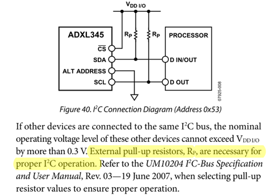
    Please make sure that your hardware connection for this I2C device is connected properly (for example, like mentioned in datasheet: With CS tied high to V DD I/O, the ADXL345 is in I2C mode)

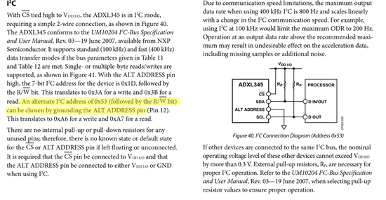
    One thing that I am wondering, in the datasheet it seems not mentioned how many byte the Register Address is (yellow box in the picture below). If the register address is one byte, it means you should modify the example of ControlSuite because it uses 2 bytes address. Maybe this is the case that this I2C only uses one byte address for accessing its registers.

    You can try and please tell us what you get. Also you can send your modification code here that maybe we can find something to suggest you more.

    Best regards,

    Maria


  • HI everyone
    In here, i'm so appreciate everyone take care my problem but i can't find my mistake still.
    #include "DSP28x_Project.h"
    void I2C_Init(void);
    void I2C_Write(void);
    void I2C_Read(void);
    interrupt void i2c_int1a_isr(void);
    
    #define SLAVE_ADDR        	  0x50 //ADXL345
    #define Register_2D           0x2D
    #define Register_X0           0x32
    #define Register_X1           0x33
    #define Register_Y0           0x34
    #define Register_Y1           0x35
    #define Register_Z0           0x36
    #define Register_Z1           0x37
    #define HIGH_ADDR			  0x03
    
    Uint16 DATA[2];
    Uint16 i2cStatus = 0;
    Uint16 interrupt_SCD = 0;
    Uint16 interrupt_ARDY = 0;
    
    void main(void)
    
    {
    	Uint16 i;
    	InitSysCtrl();
    	InitI2CGpio();
    	DINT;
    	InitPieCtrl();
    
    // Disable CPU interrupts and clear all CPU interrupt flags:
    
       IER = 0x0000;
       IFR = 0x0000;
    
       InitPieVectTable();
    
       EALLOW;	// This is needed to write to EALLOW protected registers
       PieVectTable.I2CINT1A = &i2c_int1a_isr;
       EDIS;   // This is needed to disable write to EALLOW protected registers
       I2C_Init();
       for(i=0;i<2;i++)
       {
           DATA[i]=0x0000;
       }
       // Enable interrupts required for this example
       // Enable I2C interrupt 1 in the PIE: Group 8 interrupt 1
       PieCtrlRegs.PIEIER8.bit.INTx1 = 1;
    
       // Enable CPU INT8 which is connected to PIE group 8
       IER |= M_INT8;
       EINT;
    
       I2C_Write();
    
       for(;;)
       {
    	   I2C_Read();
       }   // end of for(;;)
    
    }   // end of main
    
    
    void I2C_Init(void)
    {
       // Initialize I2C
       I2caRegs.I2CSAR = SLAVE_ADDR;// Slave address - EEPROM control code
       I2caRegs.I2COAR = 0x19;			// Master address
    
       #if (CPU_FRQ_150MHZ)             // Default - For 150MHz SYSCLKOUT
            I2caRegs.I2CPSC.all = 14;   // Prescaler - need 7-12 Mhz on module clk (150/15 = 10MHz)
       #endif
       #if (CPU_FRQ_100MHZ)             // For 100 MHz SYSCLKOUT
         I2caRegs.I2CPSC.all = 9;	    // Prescaler - need 7-12 Mhz on module clk (100/10 = 10MHz)
       #endif
    
       I2caRegs.I2CCLKL = 10;			// NOTE: must be non zero
       I2caRegs.I2CCLKH = 5;			// NOTE: must be non zero
       I2caRegs.I2CIER.all = 0x24;		// Enable SCD & ARDY interrupts
    
       I2caRegs.I2CMDR.all = 0x0020;	// Take I2C out of reset
       									// Stop I2C when suspended
    									// I2caRegs.I2CMDR.all = 0000 0010 0000 0000
    
       I2caRegs.I2CFFTX.all = 0x6000;	// Enable FIFO mode and TXFIFO
       I2caRegs.I2CFFRX.all = 0x2040;	// Enable RXFIFO, clear RXFFINT,
    
       return;
    }
    
    void I2C_Write(void)
    {
    	I2caRegs.I2CCNT = 3;
    	I2caRegs.I2CSAR = SLAVE_ADDR;          //Select POWER_CTL register in sensor
    	I2caRegs.I2CDXR = HIGH_ADDR;
    	I2caRegs.I2CDXR = Register_2D;
    	I2caRegs.I2CDXR = 0xA;
    	I2caRegs.I2CMDR.all = 0x6E20;           //Generate start and stop, master transmitter
    	while(I2caRegs.I2CSTR.bit.SCD == 0);    // wait for STOP condition
    	I2caRegs.I2CSTR.bit.SCD = 1;
    }
    
    void I2C_Read(void)
    {
    	I2caRegs.I2CSAR = SLAVE_ADDR;
    	I2caRegs.I2CDXR = HIGH_ADDR;
    	I2caRegs.I2CDXR = Register_X0;
    	I2caRegs.I2CCNT = 2;
    	I2caRegs.I2CMDR.all = 0x6620; //0110 0110 0010 0000
    	i2cStatus = 1;
    	while(I2caRegs.I2CSTR.bit.BB == 1)
    	{}
        I2caRegs.I2CCNT = 1;	// Setup how many bytes to expect
        I2caRegs.I2CMDR.all = 0x6C20; //0010 1100 0010 0000 Send restart as master receiver
        i2cStatus = 1;
        while(I2caRegs.I2CSTR.bit.BB == 1)
        {
        	DATA[1]=I2caRegs.I2CDRR;
        }
        if(i2cStatus == 2)
        {
        	//I2caRegs.I2CMDR.bit.IRS = 0;
        }
    }
    
    interrupt void i2c_int1a_isr(void)     // I2C-A
    {
    	// Read interrupt source
    	Uint16 IntSource;
    	IntSource = I2caRegs.I2CISRC.all;
    	// Interrupt source = Register Access Ready
    	// This interrupt is used to determine when the EEPROM address setup portion of the
    	// read data communication is complete. Since no stop bit is commanded, this flag
    	// tells us when the message has been sent instead of the SCD flag. If a NACK is
    	// received, clear the NACK bit and command a stop. Otherwise, move on to the read
    	// data portion of the communication.
    	if(IntSource == I2C_SCD_ISRC)
    	{
    		interrupt_SCD++;
    	}
    	else if(IntSource == I2C_ARDY_ISRC)
    	{
    		interrupt_ARDY++;
    		if(I2caRegs.I2CSTR.bit.NACK == 1)
    		{
    			I2caRegs.I2CMDR.bit.STP = 1;
    			I2caRegs.I2CSTR.all = I2C_CLR_NACK_BIT;
    			i2cStatus = 2;
    		}
    		else if(i2cStatus == 1)
    		{
    			i2cStatus = 0;
    		}
    	}  // end of register access ready
    
    	/*else
    	{
          // Generate some error due to invalid interrupt source
    		asm("   ESTOP0");
    	}*/
    
    	// Enable future I2C (PIE Group 8) interrupts
    	PieCtrlRegs.PIEACK.all = PIEACK_GROUP8;
    }
    
    //==================== =======================================================
    
    // No more.
    
    //===========================================================================
    

  • Hello Alex,

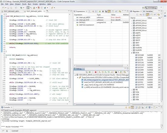
    Can you try this file and let me know what you observe using debugger (for example if it is stuck, in which line it is stucked, and give the screenshot of the I2C registers content).

    3247.i2c-adxl345.c
    #include "DSP28x_Project.h"
    void I2C_Init(void);
    void I2C_Write(Uint16 reg_address, Uint16 data);
    Uint16 I2C_Read(Uint16 reg_address);
    
    
    #define SLAVE_ADDR            0x53 //ADXL345 -> if ALT_ADDRESS pin is grounded!
    #define Register_2D           0x2D
    #define Register_X0           0x32
    #define Register_X1           0x33
    #define Register_Y0           0x34
    #define Register_Y1           0x35
    #define Register_Z0           0x36
    #define Register_Z1           0x37
    
    
    Uint16 DATA[2];
    
    
    void main(void)
    {
        Uint16 i;
        InitSysCtrl();
        InitI2CGpio();
        DINT;
        InitPieCtrl();
    // Disable CPU interrupts and clear all CPU interrupt flags:
       IER = 0x0000;
       IFR = 0x0000;
       InitPieVectTable();
    
       I2C_Init();
       for(i=0;i<2;i++)
       {
           DATA[i]=0x0000;
       }
    
       EINT;
       I2C_Write(Register_2D, 0x0A);			// send data 0x0A to register address 2D
       for(;;)
       {
           DATA[0] = I2C_Read(Register_2D);	// read register address 2D
       }   // end of for(;;)
    }   // end of main
    void I2C_Init(void)
    {
       // Initialize I2C
       I2caRegs.I2CMDR.all 	= 0x0000;
       I2caRegs.I2CSAR = SLAVE_ADDR;// Slave address - EEPROM control code
       //I2caRegs.I2COAR = 0x19;          // Master address
       #if (CPU_FRQ_150MHZ)             // Default - For 150MHz SYSCLKOUT
            I2caRegs.I2CPSC.all = 14;   // Prescaler - need 7-12 Mhz on module clk (150/15 = 10MHz)
       #endif
       #if (CPU_FRQ_100MHZ)             // For 100 MHz SYSCLKOUT
         I2caRegs.I2CPSC.all = 9;       // Prescaler - need 7-12 Mhz on module clk (100/10 = 10MHz)
       #endif
       I2caRegs.I2CCLKL = 10;           // NOTE: must be non zero
       I2caRegs.I2CCLKH = 5;            // NOTE: must be non zero
    
       I2caRegs.I2CMDR.all = 0x0020;    // Take I2C out of reset
                                        // Stop I2C when suspended
                                        // I2caRegs.I2CMDR.all = 0000 0010 0000 0000
       I2caRegs.I2CFFTX.all = 0x6000;   // Enable FIFO mode and TXFIFO
       I2caRegs.I2CFFRX.all = 0x2040;   // Enable RXFIFO, clear RXFFINT,
       return;
    }
    void I2C_Write(Uint16 reg_address, Uint16 data)
    {
    	I2caRegs.I2CMDR.bit.IRS = 1; 			// reset I2C
    	
    	I2caRegs.I2CSAR = SLAVE_ADDR;           // I2C slave address
    	while (I2caRegs.I2CSTR.bit.BB == 1);	// still busy?
    	
        I2caRegs.I2CCNT = 2;					// assume register address = 1 byte, and data is 1 byte
    	I2caRegs.I2CMDR.all = 0x6E20; 			// start, stop, no rm, reset i2c
        I2caRegs.I2CDXR = reg_address;			// register address of the sensor (1 byte)
        I2caRegs.I2CDXR = data;					// data to be sent (1 byte)
    	
    	I2caRegs.I2CMDR.bit.STP = 1;  			// stop bit when CNT=0
        
        while(!I2caRegs.I2CSTR.bit.SCD);       // wait for STOP condition
    	
    	return;
    
    }
    
    Uint16 I2C_Read(Uint16 reg_address)
    {
    	Uint16 tempdata;
    
    	I2caRegs.I2CMDR.bit.IRS = 1; 				// reset I2C
    	
    	// Make sure I2C is not busy and has stopped
    	I2caRegs.I2CMDR.bit.IRS = 1; 				// reset I2C
    	while (I2caRegs.I2CSTR.bit.BB == 1);		// busy loop
    	I2caRegs.I2CSTR.bit.SCD = 1;				// Clear the SCD bit (stop condition bit)
    	while(I2caRegs.I2CMDR.bit.STP == 1);		// stop bit loop
    	
    	I2caRegs.I2CSAR 	= SLAVE_ADDR;			// I2C slave address
    
    	while (I2caRegs.I2CSTR.bit.BB == 1);		// still busy?
    	
    	I2caRegs.I2CMDR.all = 0x2620;				// start, no stop bit, master, tx, reset I2C
    	I2caRegs.I2CCNT		= 1;					// assume register address is one byte
    	I2caRegs.I2CDXR		= reg_address;			// register address of the sensor (1 byte)
    
    	while(!I2caRegs.I2CSTR.bit.ARDY);			// all ready?
    
    	I2caRegs.I2CMDR.all = 0x2C20;				// start, stop bit when CNT =0, master, rx, reset I2C
    	I2caRegs.I2CCNT		= 1;					// only read one byte data
    
    	if(I2caRegs.I2CSTR.bit.NACK == 1)
    	{
    		 I2caRegs.I2CSTR.all = I2C_CLR_NACK_BIT; 	// 0x0002
    	}
    	I2caRegs.I2CMDR.bit.STP = 1;					// stop bit when CNT=0
    
    	while(!I2caRegs.I2CSTR.bit.SCD);				// stop bit detected?
    
    				
    	tempdata	= I2caRegs.I2CDRR;					// read one byte data
    
    
    	return(tempdata);
     
    }
    i
    //==================== =======================================================
    // No more.
    //===========================================================================
    Best regards,

    Maria

  • HI Maria Todorova

    Here is the result. Coding is stuck in "while(!I2c Regs.I2C START.bit.SCD);" and the register I2CDRR doesn't change

  • HELLO Maria

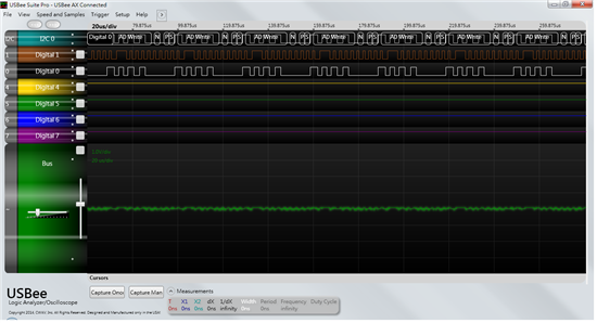
    Here is my code, it can generate the signal but it's wrong.

    #include "DSP28x_Project.h"
    void I2C_Init(void);
    void I2C_Write(void);
    void I2C_Read(void);
    interrupt void i2c_int1a_isr(void);
    
    #define SLAVE_ADDR        	  0x50 //ADXL345
    #define W_HI_ADD              0xA0
    #define R_HI_ADD              0xA0
    #define W_LO_ADD              0x06
    #define R_LO_ADD              0x07
    #define Register_2D           0x2D
    #define Register_X0           0x32
    #define Register_X1           0x33
    #define Register_Y0           0x34
    #define Register_Y1           0x35
    #define Register_Z0           0x36
    #define Register_Z1           0x37
    #define HIGH_ADDR			  0x03
    
    Uint16 DATA[2];
    Uint16 i2cStatus = 0;
    Uint16 interrupt_SCD = 0;
    Uint16 interrupt_ARDY = 0;
    
    void main(void)
    
    {
    	Uint16 i;
    	InitSysCtrl();
    	InitI2CGpio();
    	DINT;
    	InitPieCtrl();
    
    // Disable CPU interrupts and clear all CPU interrupt flags:
    
       IER = 0x0000;
       IFR = 0x0000;
    
       InitPieVectTable();
    
       EALLOW;	// This is needed to write to EALLOW protected registers
       PieVectTable.I2CINT1A = &i2c_int1a_isr;
       EDIS;   // This is needed to disable write to EALLOW protected registers
       I2C_Init();
       for(i=0;i<2;i++)
       {
           DATA[i]=0x0000;
       }
       // Enable interrupts required for this example
       // Enable I2C interrupt 1 in the PIE: Group 8 interrupt 1
       PieCtrlRegs.PIEIER8.bit.INTx1 = 1;
    
       // Enable CPU INT8 which is connected to PIE group 8
       IER |= M_INT8;
       EINT;
    
       I2C_Write();
    
       for(;;)
       {
    	   I2C_Read();
       }   // end of for(;;)
    
    }   // end of main
    
    
    void I2C_Init(void)
    {
       // Initialize I2C
       I2caRegs.I2CSAR = SLAVE_ADDR;// Slave address - EEPROM control code
    
       I2caRegs.I2COAR = 0x19;			// Master address
    
       #if (CPU_FRQ_150MHZ)             // Default - For 150MHz SYSCLKOUT
            I2caRegs.I2CPSC.all = 14;   // Prescaler - need 7-12 Mhz on module clk (150/15 = 10MHz)
       #endif
       #if (CPU_FRQ_100MHZ)             // For 100 MHz SYSCLKOUT
         I2caRegs.I2CPSC.all = 9;	    // Prescaler - need 7-12 Mhz on module clk (100/10 = 10MHz)
       #endif
    
       I2caRegs.I2CCLKL = 10;			// NOTE: must be non zero
       I2caRegs.I2CCLKH = 5;			// NOTE: must be non zero
       I2caRegs.I2CIER.all = 0x24;		// Enable SCD & ARDY interrupts
    
       I2caRegs.I2CMDR.all = 0x0020;	// Take I2C out of reset
       									// Stop I2C when suspended
    									// I2caRegs.I2CMDR.all = 0000 0010 0000 0000
    
       I2caRegs.I2CFFTX.all = 0x6000;	// Enable FIFO mode and TXFIFO
       I2caRegs.I2CFFRX.all = 0x2040;	// Enable RXFIFO, clear RXFFINT,
    
       return;
    }
    
    void I2C_Write(void)
    {
    	I2caRegs.I2CCNT = 3;
    	I2caRegs.I2CSAR = SLAVE_ADDR;          //Select POWER_CTL register in sensor
    	I2caRegs.I2CDXR = HIGH_ADDR;
    	I2caRegs.I2CDXR = Register_2D;
    	I2caRegs.I2CDXR = 0x0A;
    	I2caRegs.I2CMDR.all = 0x6E20;           //Generate start and stop, master transmitter
    	while(I2caRegs.I2CSTR.bit.SCD == 0);    // wait for STOP condition
    	I2caRegs.I2CSTR.bit.SCD = 1;
    }
    
    void I2C_Read(void)
    {
    	I2caRegs.I2CSAR = SLAVE_ADDR;
    	I2caRegs.I2CDXR = HIGH_ADDR;
    	I2caRegs.I2CDXR = Register_X1;
    	I2caRegs.I2CCNT = 2;
    	I2caRegs.I2CMDR.all = 0x6620; //0110 0110 0010 0000
    	i2cStatus = 1;
    	while(I2caRegs.I2CSTR.bit.BB == 1)
    	{}
        I2caRegs.I2CCNT = 1;	// Setup how many bytes to expect
        I2caRegs.I2CMDR.all = 0x6C20; //0010 1100 0010 0000 Send restart as master receiver
        i2cStatus = 1;
        while(I2caRegs.I2CSTR.bit.BB == 1)
        {
        	DATA[1]=I2caRegs.I2CDRR;
        }
        if(i2cStatus == 2)
        {
        	//I2caRegs.I2CMDR.bit.IRS = 0;
        }
    }
    
    interrupt void i2c_int1a_isr(void)     // I2C-A
    {
    	// Read interrupt source
    	Uint16 IntSource;
    	IntSource = I2caRegs.I2CISRC.all;
    	// Interrupt source = Register Access Ready
    	// This interrupt is used to determine when the EEPROM address setup portion of the
    	// read data communication is complete. Since no stop bit is commanded, this flag
    	// tells us when the message has been sent instead of the SCD flag. If a NACK is
    	// received, clear the NACK bit and command a stop. Otherwise, move on to the read
    	// data portion of the communication.
    	if(IntSource == I2C_SCD_ISRC)
    	{
    		interrupt_SCD++;
    	}
    	else if(IntSource == I2C_ARDY_ISRC)
    	{
    
    		if(I2caRegs.I2CSTR.bit.NACK == 1)
    		{
    			I2caRegs.I2CMDR.bit.STP = 1;
    			I2caRegs.I2CSTR.all = I2C_CLR_NACK_BIT;
    			i2cStatus = 2;
    			interrupt_ARDY++;
    		}
    		else if(i2cStatus == 1)
    		{
    			i2cStatus = 0;
    		}
    	}  // end of register access ready
    
    	/*else
    	{
          // Generate some error due to invalid interrupt source
    		asm("   ESTOP0");
    	}*/
    
    	// Enable future I2C (PIE Group 8) interrupts
    	PieCtrlRegs.PIEACK.all = PIEACK_GROUP8;
    }
    
    //==================== =======================================================
    
    // No more.
    
    //===========================================================================
    

  • Alex Huang1 said:
    #define SLAVE_ADDR 0x50 //ADXL345

    Can you change the SLAVE_ADDR to become 0x53?

    Also in init function, delete this line:

    Alex Huang1 said:
    I2caRegs.I2COAR = 0x19; // Master address

  • Sergio Luna ,

    are you getting any signals on SDA n SCL ??

  • hi yanzhen fu 

    do you have any i2c example, but doesn't like the official eeprom example.

    I've changed the "SLAVE_ADDR" like you say... hi address & low address

    it's have some signal but i don't catch any data form ADXL345.


    #include "DSP28x_Project.h"
    void I2C_Init(void);
    void I2C_Write(void);
    void I2C_Read(void);
    interrupt void i2c_int1a_isr(void);
    
    #define SLAVE_ADDR        	  0x50 //ADXL345
    #define W_HI_ADD              0xA0
    #define R_HI_ADD              0xA0
    #define W_LO_ADD              0x06
    #define R_LO_ADD              0x07
    #define Register_2D           0x2D
    #define Register_X0           0x32
    #define Register_X1           0x33
    #define Register_Y0           0x34
    #define Register_Y1           0x35
    #define Register_Z0           0x36
    #define Register_Z1           0x37
    #define HIGH_ADDR			  0x03
    
    Uint16 DATA[2];
    Uint16 i2cStatus = 0;
    Uint16 interrupt_SCD = 0;
    Uint16 interrupt_ARDY = 0;
    
    void main(void)
    
    {
    	Uint16 i;
    	InitSysCtrl();
    	InitI2CGpio();
    	DINT;
    	InitPieCtrl();
    
    // Disable CPU interrupts and clear all CPU interrupt flags:
    
       IER = 0x0000;
       IFR = 0x0000;
    
       InitPieVectTable();
    
       EALLOW;	// This is needed to write to EALLOW protected registers
       PieVectTable.I2CINT1A = &i2c_int1a_isr;
       EDIS;   // This is needed to disable write to EALLOW protected registers
       I2C_Init();
       for(i=0;i<2;i++)
       {
           DATA[i]=0x0000;
       }
       // Enable interrupts required for this example
       // Enable I2C interrupt 1 in the PIE: Group 8 interrupt 1
       PieCtrlRegs.PIEIER8.bit.INTx1 = 1;
    
       // Enable CPU INT8 which is connected to PIE group 8
       IER |= M_INT8;
       EINT;
    
       I2C_Write();
    
       for(;;)
       {
    	   I2C_Read();
       }   // end of for(;;)
    
    }   // end of main
    
    
    void I2C_Init(void)
    {
       // Initialize I2C
       I2caRegs.I2CSAR = SLAVE_ADDR;// Slave address - EEPROM control code
    
       I2caRegs.I2COAR = 0x19;			// Master address
    
       #if (CPU_FRQ_150MHZ)             // Default - For 150MHz SYSCLKOUT
            I2caRegs.I2CPSC.all = 14;   // Prescaler - need 7-12 Mhz on module clk (150/15 = 10MHz)
       #endif
       #if (CPU_FRQ_100MHZ)             // For 100 MHz SYSCLKOUT
         I2caRegs.I2CPSC.all = 9;	    // Prescaler - need 7-12 Mhz on module clk (100/10 = 10MHz)
       #endif
    
       I2caRegs.I2CCLKL = 10;			// NOTE: must be non zero
       I2caRegs.I2CCLKH = 5;			// NOTE: must be non zero
       I2caRegs.I2CIER.all = 0x24;		// Enable SCD & ARDY interrupts
    
       I2caRegs.I2CMDR.all = 0x0020;	// Take I2C out of reset
       									// Stop I2C when suspended
    									// I2caRegs.I2CMDR.all = 0000 0010 0000 0000
    
       I2caRegs.I2CFFTX.all = 0x6000;	// Enable FIFO mode and TXFIFO
       I2caRegs.I2CFFRX.all = 0x2040;	// Enable RXFIFO, clear RXFFINT,
    
       return;
    }
    
    void I2C_Write(void)
    {
    	I2caRegs.I2CCNT = 3;
    	I2caRegs.I2CSAR = SLAVE_ADDR;          //Select POWER_CTL register in sensor
    	I2caRegs.I2CDXR = HIGH_ADDR;
    	I2caRegs.I2CDXR = Register_2D;
    	I2caRegs.I2CDXR = 0x0A;
    	I2caRegs.I2CMDR.all = 0x6E20;           //Generate start and stop, master transmitter
    	while(I2caRegs.I2CSTR.bit.SCD == 0);    // wait for STOP condition
    	I2caRegs.I2CSTR.bit.SCD = 1;
    }
    
    void I2C_Read(void)
    {
    	I2caRegs.I2CSAR = SLAVE_ADDR;
    	I2caRegs.I2CDXR = HIGH_ADDR;
    	I2caRegs.I2CDXR = Register_X1;
    	I2caRegs.I2CCNT = 2;
    	I2caRegs.I2CMDR.all = 0x6620; //0110 0110 0010 0000
    	i2cStatus = 1;
    	while(I2caRegs.I2CSTR.bit.BB == 1)
    	{}
        I2caRegs.I2CCNT = 1;	// Setup how many bytes to expect
        I2caRegs.I2CMDR.all = 0x6C20; //0010 1100 0010 0000 Send restart as master receiver
        i2cStatus = 1;
        while(I2caRegs.I2CSTR.bit.BB == 1)
        {
        	DATA[1]=I2caRegs.I2CDRR;
        }
        if(i2cStatus == 2)
        {
        	//I2caRegs.I2CMDR.bit.IRS = 0;
        }
    }
    
    interrupt void i2c_int1a_isr(void)     // I2C-A
    {
    	// Read interrupt source
    	Uint16 IntSource;
    	IntSource = I2caRegs.I2CISRC.all;
    	// Interrupt source = Register Access Ready
    	// This interrupt is used to determine when the EEPROM address setup portion of the
    	// read data communication is complete. Since no stop bit is commanded, this flag
    	// tells us when the message has been sent instead of the SCD flag. If a NACK is
    	// received, clear the NACK bit and command a stop. Otherwise, move on to the read
    	// data portion of the communication.
    	if(IntSource == I2C_SCD_ISRC)
    	{
    		interrupt_SCD++;
    	}
    	else if(IntSource == I2C_ARDY_ISRC)
    	{
    
    		if(I2caRegs.I2CSTR.bit.NACK == 1)
    		{
    			I2caRegs.I2CMDR.bit.STP = 1;
    			I2caRegs.I2CSTR.all = I2C_CLR_NACK_BIT;
    			i2cStatus = 2;
    			interrupt_ARDY++;
    		}
    		else if(i2cStatus == 1)
    		{
    			i2cStatus = 0;
    		}
    	}  // end of register access ready
    
    	/*else
    	{
          // Generate some error due to invalid interrupt source
    		asm("   ESTOP0");
    	}*/
    
    	// Enable future I2C (PIE Group 8) interrupts
    	PieCtrlRegs.PIEACK.all = PIEACK_GROUP8;
    }
    
    //==================== =======================================================
    
    // No more.
    
    //===========================================================================


  • hi Maria Todorova

    when i change the SLAVE_ADDR to become 0x53 it will lost all signal 

    and i try delet  I2caRegs.I2COAR = 0x19; this line 

    it's still doesn't work.

    .

  • Hello Alex Huang,

    I am not sure you are understand about SLAVE ADDRESS or not.

    The SLAVE ADDRESS of this sensor (ADXL345) are only two options based on the datasheet (0x53 or 0x1D), this depends on  ALT ADDRESS pin.

    Please tell me how you connect your ADXL345 (schematic). Make sure your ADXL345 is setup (hardware) properly first, then you can continue to firmware.

    Also you can refer to this link about this sensor firmware (it provides code for Arduino)

    http://www.i2cdevlib.com/devices/adxl345#source

    Best regards,

    Maria

  • hi Maria Todorova

    ok, i'm pretty sure if i change the SLAVE ADDRESS to 0x53 my signal will lost

    because i've use logic analyzer measure it.

    ok, I'll still try but  i'm so curious... have you ever use ti 28x dsp?

  • hi Maria

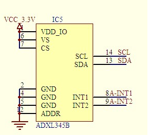
    here is my schematic, about ADXL345

  • Hello Alex,

    Can you put pull-up resistors for SCL and SDA? Because it is necessary, based on the datasheet.

    Best regards,

    Maria

  • And after that you can try this code.

    Unfortunately I don't have this sensor to try so I can not try it by myself.

    5367.i2c-adxl345-2.c
    #include "DSP28x_Project.h"
    void I2C_Init(void);
    void I2C_Write(Uint16 reg_address, Uint16 data);
    Uint16 I2C_Read(Uint16 reg_address);
    
    
    #define SLAVE_ADDR            0x53 //ADXL345 -> if ALT_ADDRESS pin is grounded!
    #define Register_2D           0x2D
    #define Register_X0           0x32
    #define Register_X1           0x33
    #define Register_Y0           0x34
    #define Register_Y1           0x35
    #define Register_Z0           0x36
    #define Register_Z1           0x37
    
    
    Uint16 DATA[6];
    
    
    void main(void)
    {
        Uint16 i;
        InitSysCtrl();
        InitI2CGpio();
        DINT;
        InitPieCtrl();
    // Disable CPU interrupts and clear all CPU interrupt flags:
       IER = 0x0000;
       IFR = 0x0000;
       InitPieVectTable();
    
       I2C_Init();
       for(i=0;i<2;i++)
       {
           DATA[i]=0x0000;
       }
    
       EINT;
    //   I2C_Write(Register_2D, 0x00);			// send data 0x00 to register address 2D (standby mode)
       
       I2C_Write(Register_2D, 0x08);			// send data 0x00 to register address 2D (measure mode)
       
       for(;;)
       {
           DATA[0] = I2C_Read(Register_X0);	// read register address X0
    	   DATA[1] = I2C_Read(Register_X1);	// read register address X1
    	   DATA[2] = I2C_Read(Register_Y0);	// read register address Y0
    	   DATA[3] = I2C_Read(Register_Y1);	// read register address Y1
    	   DATA[4] = I2C_Read(Register_Z0);	// read register address Z0
    	   DATA[5] = I2C_Read(Register_Z1);	// read register address Z1
       }   // end of for(;;)
    }   // end of main
    void I2C_Init(void)
    {
       // Initialize I2C
       I2caRegs.I2CMDR.all 	= 0x0020;
       I2caRegs.I2CSAR = SLAVE_ADDR;// Slave address - EEPROM control code
      
       #if (CPU_FRQ_150MHZ)             // Default - For 150MHz SYSCLKOUT
            I2caRegs.I2CPSC.all = 14;   // Prescaler - need 7-12 Mhz on module clk (150/15 = 10MHz)
       #endif
       #if (CPU_FRQ_100MHZ)             // For 100 MHz SYSCLKOUT
         I2caRegs.I2CPSC.all = 9;       // Prescaler - need 7-12 Mhz on module clk (100/10 = 10MHz)
       #endif
       I2caRegs.I2CCLKL = 10;           // NOTE: must be non zero
       I2caRegs.I2CCLKH = 5;            // NOTE: must be non zero
    
       I2caRegs.I2CMDR.all = 0x0020;    // Take I2C out of reset
                                        // Stop I2C when suspended
                                        // I2caRegs.I2CMDR.all = 0000 0010 0000 0000
       I2caRegs.I2CFFTX.all = 0x6000;   // Enable FIFO mode and TXFIFO
       I2caRegs.I2CFFRX.all = 0x2040;   // Enable RXFIFO, clear RXFFINT,
       return;
    }
    void I2C_Write(Uint16 reg_address, Uint16 data)
    {
    	I2caRegs.I2CMDR.bit.IRS = 1; 			// reset I2C
    	
    	I2caRegs.I2CSAR = SLAVE_ADDR;           // I2C slave address
    	while (I2caRegs.I2CSTR.bit.BB == 1);	// still busy?
    	
        I2caRegs.I2CCNT = 2;					// assume register address = 1 byte, and data is 1 byte
    	
        I2caRegs.I2CDXR = reg_address;			// register address of the sensor (1 byte)
        I2caRegs.I2CDXR = data;					// data to be sent (1 byte)
    	
    	I2caRegs.I2CMDR.all = 0x2E20; 			// start, stop, no rm, reset i2c
    	
    	I2caRegs.I2CMDR.bit.STP = 1;  			// stop bit when CNT=0
        
        while(!I2caRegs.I2CSTR.bit.SCD);       // wait for STOP condition
    
    	
    	return;
    
    }
    
    
    Uint16 I2C_Read(Uint16 reg_address)
    {
    	Uint16 tempdata;
    
    	I2caRegs.I2CMDR.bit.IRS = 1; 				// reset I2C
    	
    	// Make sure I2C is not busy and has stopped
    	I2caRegs.I2CMDR.bit.IRS = 1; 				// reset I2C
    	while (I2caRegs.I2CSTR.bit.BB == 1);		// busy loop
    	I2caRegs.I2CSTR.bit.SCD = 1;				// Clear the SCD bit (stop condition bit)
    	while(I2caRegs.I2CMDR.bit.STP == 1);		// stop bit loop
    	
    	I2caRegs.I2CSAR 	= SLAVE_ADDR;			// I2C slave address
    
    	while (I2caRegs.I2CSTR.bit.BB == 1);		// still busy?
    	
    	I2caRegs.I2CMDR.all = 0x2620;				// start, no stop bit, master, tx, reset I2C
    	I2caRegs.I2CCNT		= 1;					// assume register address is one byte
    	I2caRegs.I2CDXR		= reg_address;			// register address of the sensor (1 byte)
    
    	while(!I2caRegs.I2CSTR.bit.ARDY);			// all ready?
    
    	I2caRegs.I2CMDR.all = 0x2C20;				// start, stop bit when CNT =0, master, rx, reset I2C
    	I2caRegs.I2CCNT		= 1;					// only read one byte data
    
    	if(I2caRegs.I2CSTR.bit.NACK == 1)
    	{
    		 I2caRegs.I2CSTR.all = I2C_CLR_NACK_BIT; 	// 0x0002
    	}
    	I2caRegs.I2CMDR.bit.STP = 1;					// stop bit when CNT=0
    
    	while(!I2caRegs.I2CSTR.bit.SCD);				// stop bit detected?
    
    				
    	tempdata	= I2caRegs.I2CDRR;					// read one byte data
    
    
    	return(tempdata);
     
    }
    i
    //==================== =======================================================
    // No more.
    //===========================================================================

    Best regards,

    Maria

  • hello Maria

    Here is my circuit of ADXL345

  • hellow Maria 

    I've try to use your code, but it's doesn't work

    it's can not get into the interrupt

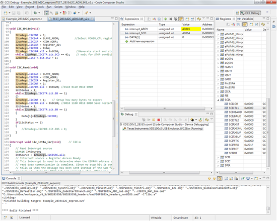
    I write a new code, but i can't get into the ARDY interrupt when i'm read i2c data function.

    #include "DSP28x_Project.h"
    void I2C_Init(void);
    void I2C_Write(void);
    void I2C_Read(void);
    interrupt void i2c_int1a_isr(void);
    
    #define SLAVE_ADDR        	  0x53 //ADXL345
    #define W_HI_ADD              0xA0
    #define R_HI_ADD              0xA0
    #define W_LO_ADD              0x06
    #define R_LO_ADD              0x07
    #define Register_2D           0x2D
    #define Register_X0           0x32
    #define Register_X1           0x33
    #define Register_Y0           0x34
    #define Register_Y1           0x35
    #define Register_Z0           0x36
    #define Register_Z1           0x37
    
    #define i2c_msg_wACT          0
    #define i2c_msg_wBusy         1
    
    #define i2c_msg_rACT          3
    #define i2c_msg_rWBusy        4
    #define i2c_msg_rREST         5
    #define i2c_msg_rRBusy        6
    
    #define I2C_CLR_NACK_BIT      0x0002
    #define I2C_ARDY_ISRC         0x0003
    #define I2C_SCD_ISRC          0x0006
    
    
    Uint16 DATA[2];
    Uint16 i2cStatus = 0;
    Uint16 interrupt_SCD = 0;
    Uint16 interrupt_ARDY = 0;
    
    void main(void)
    
    {
    	Uint16 i;
    	InitSysCtrl();
    	InitI2CGpio();
    	DINT;
    	InitPieCtrl();
    
    // Disable CPU interrupts and clear all CPU interrupt flags:
    
       IER = 0x0000;
       IFR = 0x0000;
    
       InitPieVectTable();
    
       EALLOW;	// This is needed to write to EALLOW protected registers
       PieVectTable.I2CINT1A = &i2c_int1a_isr;
       EDIS;   // This is needed to disable write to EALLOW protected registers
    
       I2C_Init();
       for(i=0;i<2;i++)
       {
           DATA[i]=0x0000;
       }
       // Enable interrupts required for this example
       // Enable I2C interrupt 1 in the PIE: Group 8 interrupt 1
       PieCtrlRegs.PIEIER8.bit.INTx1 = 1;
    
       // Enable CPU INT8 which is connected to PIE group 8
       IER |= M_INT8;
       EINT;
    
       I2C_Write();
    
       for(;;)
       {
    	   I2C_Read();
       }   // end of for(;;)
    
    }   // end of main
    
    
    void I2C_Init(void)
    {
       // Initialize I2C
       I2caRegs.I2CSAR = SLAVE_ADDR;// Slave address - EEPROM control code
    
       //I2caRegs.I2COAR = 0x19;			// Master address
    
       #if (CPU_FRQ_150MHZ)             // Default - For 150MHz SYSCLKOUT
            I2caRegs.I2CPSC.all = 14;   // Prescaler - need 7-12 Mhz on module clk (150/15 = 10MHz)
       #endif
       #if (CPU_FRQ_100MHZ)             // For 100 MHz SYSCLKOUT
         I2caRegs.I2CPSC.all = 9;	    // Prescaler - need 7-12 Mhz on module clk (100/10 = 10MHz)
       #endif
    
       I2caRegs.I2CCLKL = 10;			// NOTE: must be non zero
       I2caRegs.I2CCLKH = 5;			// NOTE: must be non zero
       I2caRegs.I2CIER.all = 0x24;		// Enable SCD & ARDY interrupts
    
       I2caRegs.I2CMDR.all = 0x0020;	// Take I2C out of reset
       									// Stop I2C when suspended
    									// I2caRegs.I2CMDR.all = 0000 0010 0000 0000
    
       I2caRegs.I2CFFTX.all = 0x6000;	// Enable FIFO mode and TXFIFO, 0110 0000 0000 0000
       I2caRegs.I2CFFRX.all = 0x2040;	// Enable RXFIFO, clear RXFFINT, 0010 0000 0100 0000
    
       i2cStatus=i2c_msg_wACT;
    
       return;
    }
    
    void I2C_Write(void)
    {
    	if(i2cStatus==i2c_msg_wACT)
    	{
    		I2caRegs.I2CCNT = 2;
    		I2caRegs.I2CSAR = SLAVE_ADDR;          //Select POWER_CTL register in sensor
    		//I2caRegs.I2CDXR = HIGH_ADDR;
    		I2caRegs.I2CDXR = Register_2D;
    		I2caRegs.I2CDXR = 0x0A;
    		I2caRegs.I2CMDR.all = 0x6E20;           //Generate start and stop, master transmitter
    		i2cStatus=i2c_msg_wBusy;
    	}
    	while(1)    // wait for STOP condition
    	{
    		if(i2cStatus==i2c_msg_rACT)
    		{
    			break;
    		}
    	}
    }
    
    void I2C_Read(void)
    {
    	if(i2cStatus == i2c_msg_rACT)
    	{
    		I2caRegs.I2CSAR = SLAVE_ADDR;
    		//I2caRegs.I2CDXR = Register_Y0;
    		I2caRegs.I2CDXR = Register_Y1;
    		//I2caRegs.I2CCNT = 2;
    		I2caRegs.I2CCNT = 1;
    		//I2caRegs.I2CMDR.all = 0x2620; //0110 0110 0010 0000
    		I2caRegs.I2CMDR.all = 0x2620; //0110 0110 0010 0000
    		i2cStatus = i2c_msg_rWBusy;
    		while(1)    // wait for STOP condition
    		{
    			if(i2cStatus==i2c_msg_rREST)
    			{
    				break;
    			}
    		}
    	}
    
    	else if(i2cStatus == i2c_msg_rREST)
    	{
    		i2cStatus = 2;
    		I2caRegs.I2CCNT = 1;	// Setup how many bytes to expect
    	    //I2caRegs.I2CMDR.all = 0x2C20; //0010 1100 0010 0000 Send restart as master receive
    	    I2caRegs.I2CMDR.all = 0x2E20; //0010 1110 0010 0000 Send restart as master receive
    	    i2cStatus=i2c_msg_rRBusy;
    		while(1)    // wait for STOP condition
    		{
    			if(i2cStatus==i2c_msg_rACT)
    			{
    				break;
    			}
    		}
    
    	}
    
    }
    
    interrupt void i2c_int1a_isr(void)     // I2C-A
    {
    	// Read interrupt source
    	Uint16 IntSource;
    	IntSource = I2caRegs.I2CISRC.all;
    	// Interrupt source = Register Access Ready
    	// This interrupt is used to determine when the EEPROM address setup portion of the
    	// read data communication is complete. Since no stop bit is commanded, this flag
    	// tells us when the message has been sent instead of the SCD flag. If a NACK is
    	// received, clear the NACK bit and command a stop. Otherwise, move on to the read
    	// data portion of the communication.
    	if(IntSource == I2C_SCD_ISRC)
    	{
    		if(i2cStatus==i2c_msg_wBusy)
    		{
    			i2cStatus=i2c_msg_rACT;
    			interrupt_SCD++;
    		}
    		else
    		{
    			if(i2cStatus==i2c_msg_rRBusy)
    			{
    				DATA[1]=I2caRegs.I2CDRR;
    				i2cStatus=i2c_msg_rACT;
    			}
    
    		}
    	}
    	else if(IntSource == I2C_ARDY_ISRC)
    	{
    		interrupt_ARDY++;
    
    		if(I2caRegs.I2CSTR.bit.NACK == 1)
    		{
    			I2caRegs.I2CMDR.bit.STP = 1;
    			I2caRegs.I2CSTR.all = I2C_CLR_NACK_BIT;
    		}
    		else if(i2cStatus==i2c_msg_rWBusy)
    		{
    			i2cStatus=i2c_msg_rREST;
    		}
    	}  // end of register access ready
    
    	/*else
    	{
          // Generate some error due to invalid interrupt source
    		asm("   ESTOP0");
    	}*/
    
    	// Enable future I2C (PIE Group 8) interrupts
    	PieCtrlRegs.PIEACK.all = PIEACK_GROUP8;
    }
    
    //==================== =======================================================
    
    // No more.
    
    //===========================================================================

  • Hello Alex Huang,

    What GPIO pins that you use for connecting I2C (SDA and SCL)? Did you check their settings?

    I saw that you connect 3 sensors to I2C bus. Did you already try the others?

    Can you check the voltage level of VCC_3.3V?

    Anyway, for me your code makes more sense now. Don't know what we miss.

    Best regards,

    Maria

  • Hello Together,
    I also tried it in the context of peripherial explorer. Initially it did not work. After I played a bit with the frequency, and especially when I deacreased it ~ 100kHZ, it started working - I am able to read (id register) and also to write and after that read reisgisters. Hope it is helpful for you guys!

    Here you are my code fixes:

    /*****************************************************************************
    The I2C module clock determines the frequency at which the I2C module operates.
    A pro-grammable pre-scaler in the I2C module divides down the I2C input clock to
    produce the module clock. To specify the divide-down value, initialize the IPSC
    field of the pre-scaler register, I2CPSC. The resulting frequency should be in
    the range of 7 - 12 MHz and is given by:

    I2C_MODULE_CLOCK = SYSCLKOUT/(IPSC+1)
    10MHz = 150MHz/(14+1)
    ******************************************************************************/
    #if (CPU_FRQ_150MHZ) // Default - For 150MHz SYSCLKOUT
    I2caRegs.I2CPSC.all = 14; // Prescaler - need 7-12 Mhz on module clk (150/15 = 10MHz)
    #endif

    /*********************************************************************************************
    * 150MHz 50KHz 100KHz 400KHz
    * ICCL / ICCH 95/95 45/45 10/5
    * *******************************************************************************************/

    I2caRegs.I2CCLKL = 95; // NOTE: must be non zero
    I2caRegs.I2CCLKH = 95; // NOTE: must be non zero

    P.S. I have enclosed part of the document I followed up - "F2833x Inter Integrated Circuit" part of the teaching ROM
     

    I2C_conf.pdf