This thread has been locked.

If you have a related question, please click the "Ask a related question" button in the top right corner. The newly created question will be automatically linked to this question.

F28335 Error encountered when writing to flash memory

Other Parts Discussed in Thread: CONTROLSUITE

I am encountering an error when trying to program the F28335 for the first time.  I tested the firmware on an ezDSP board and it programs and runs as expected, however when I try to do this on my custom board I designed I encounter the following problem:

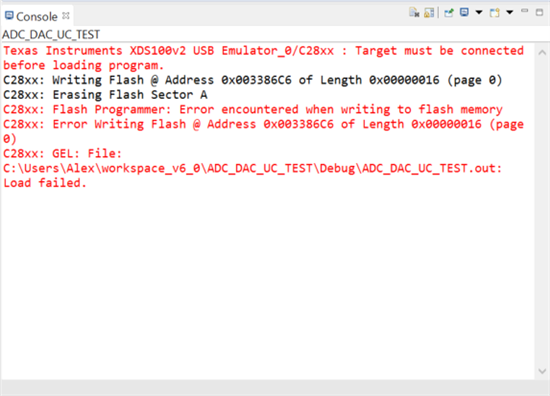
C28xx: Flash Programmer: Error encountered when writing to flash memory
C28xx: GEL: File: C:\Users\Alex\workspace_v6_0\ADC_DAC_UC_TEST\Debug\ADC_DAC_UC_TEST.out: Load failed.

This error arises when I try to load a program, I see the status "erasing flash sectors" but it remains at 0% then the error message comes up.  I have read other threads about this such as this similar post (http://e2e.ti.com/support/microcontrollers/c2000/f/171/t/295007.aspx) but it looks like their solution was to redesign the board.  I am not sure how to resolve this problem.

I am running on CCSV6

Thanks,

-Alex

  • On another note when I try to erase flash for any sector I come across this error:

    C28xx: Flash Programmer: Error erasing flash memory. Flash operation timed out waiting for the algorithm to complete. Operation cancelled.

  • Alejandro Rodriguez1 said:
    C28xx: Flash Programmer: Error erasing flash memory. Flash operation timed out waiting for the algorithm to complete. Operation cancelled.

    Is your emulator an on-board one or an external one? Also, is it XDS100v2?

    Regards,

    Gautam

  • External, and yea it is the xds100v2.

  • Alejandro Rodriguez1 said:
    External, and yea it is the xds100v2.

    Can you run the "Test Connection" in target configuration window? Just paste the results.

    Also, for the kit do you use the same external emulator or the on-board one?

    Regards,

    Gautam

  • I used the same external JTAG Debugger on both the ezDSP and on my custom board.

    These are the results from "Test Connection"

    [Start: Texas Instruments XDS100v2 USB Emulator_0]

    Execute the command:

    %ccs_base%/common/uscif/dbgjtag -f %boarddatafile% -rv -o -F inform,logfile=yes -S pathlength -S integrity

    [Result]


    -----[Print the board config pathname(s)]------------------------------------

    C:\Users\Alex\AppData\Local\TEXASI~1\CCS\
    ti\0\0\BrdDat\testBoard.dat

    -----[Print the reset-command software log-file]-----------------------------

    This utility has selected a 100- or 510-class product.
    This utility will load the adapter 'jioserdesusb.dll'.
    The library build date was 'May 21 2014'.
    The library build time was '17:19:59'.
    The library package version is '5.1.507.0'.
    The library component version is '35.34.40.0'.
    The controller does not use a programmable FPGA.
    The controller has a version number of '4' (0x00000004).
    The controller has an insertion length of '0' (0x00000000).
    This utility will attempt to reset the controller.
    This utility has successfully reset the controller.

    -----[Print the reset-command hardware log-file]-----------------------------

    The scan-path will be reset by toggling the JTAG TRST signal.
    The controller is the FTDI FT2232 with USB interface.
    The link from controller to target is direct (without cable).
    The software is configured for FTDI FT2232 features.
    The controller cannot monitor the value on the EMU[0] pin.
    The controller cannot monitor the value on the EMU[1] pin.
    The controller cannot control the timing on output pins.
    The controller cannot control the timing on input pins.
    The scan-path link-delay has been set to exactly '0' (0x0000).

    -----[The log-file for the JTAG TCLK output generated from the PLL]----------

    There is no hardware for programming the JTAG TCLK frequency.

    -----[Measure the source and frequency of the final JTAG TCLKR input]--------

    There is no hardware for measuring the JTAG TCLK frequency.

    -----[Perform the standard path-length test on the JTAG IR and DR]-----------

    This path-length test uses blocks of 512 32-bit words.

    The test for the JTAG IR instruction path-length succeeded.
    The JTAG IR instruction path-length is 38 bits.

    The test for the JTAG DR bypass path-length succeeded.
    The JTAG DR bypass path-length is 1 bits.

    -----[Perform the Integrity scan-test on the JTAG IR]------------------------

    This test will use blocks of 512 32-bit words.
    This test will be applied just once.

    Do a test using 0xFFFFFFFF.
    Scan tests: 1, skipped: 0, failed: 0
    Do a test using 0x00000000.
    Scan tests: 2, skipped: 0, failed: 0
    Do a test using 0xFE03E0E2.
    Scan tests: 3, skipped: 0, failed: 0
    Do a test using 0x01FC1F1D.
    Scan tests: 4, skipped: 0, failed: 0
    Do a test using 0x5533CCAA.
    Scan tests: 5, skipped: 0, failed: 0
    Do a test using 0xAACC3355.
    Scan tests: 6, skipped: 0, failed: 0
    All of the values were scanned correctly.

    The JTAG IR Integrity scan-test has succeeded.

    -----[Perform the Integrity scan-test on the JTAG DR]------------------------

    This test will use blocks of 512 32-bit words.
    This test will be applied just once.

    Do a test using 0xFFFFFFFF.
    Scan tests: 1, skipped: 0, failed: 0
    Do a test using 0x00000000.
    Scan tests: 2, skipped: 0, failed: 0
    Do a test using 0xFE03E0E2.
    Scan tests: 3, skipped: 0, failed: 0
    Do a test using 0x01FC1F1D.
    Scan tests: 4, skipped: 0, failed: 0
    Do a test using 0x5533CCAA.
    Scan tests: 5, skipped: 0, failed: 0
    Do a test using 0xAACC3355.
    Scan tests: 6, skipped: 0, failed: 0
    All of the values were scanned correctly.

    The JTAG DR Integrity scan-test has succeeded.

    [End: Texas Instruments XDS100v2 USB Emulator_0]

  • Yup, this means that your emulator is all fine! You'll have to check the connections between JTAG and controller on your custom board. Just verify with the schematics of your development board. There might be some minute issue that might've got ignored.

    Regards,

    Gautam

  • I've looked it over but do not see anything obviously wrong.  This is the jtag portion of my schematic:

    Is there something I am missing?

    Thanks,

    -Alex

  • Alex, the above connections seem to be very fine. Now, what about the health of the controller? Can you try replacing the controller?

    Regards,

    Gautam

  • That was also a concern of mine, and I have tried it on two different boards with the same result.

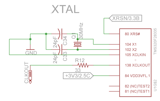
    I have a 30 Mhz crystal attached to the controller.  Does that affect the configuration in any way?  I did set up the OSCCLK in the "On Chip Flash" section to match...

    Thanks,

    -Alex

  • The above configuration seems fine too. Next comes the supply to the custom board; I hope you're using an external supply to power the board and not supply from XDS100v2.

    Regards,

    Gautam

  • Yes, I am using an external power supply to the board.  I am supplying +5V and GND then I have voltage regulators for the 3.3V and 1.8V lines.

  • Alejandro Rodriguez1 said:
    Yes, I am using an external power supply to the board.  I am supplying +5V and GND then I have voltage regulators for the 3.3V and 1.8V lines.

    What else have we left out with :)

    Just one thing, can you attach the screenshot of the exact error window?

    Regards,

    Gautam

  • Sure, and I am also going to list step by step what I am doing.

    1) Connect JTAG and power on custom board.

    2) Open Code Composer Studio 6.0.0

    3) Click on project I want to run in Project Explorer Window to set to "Active-Debug"

    4) Right-Click on project and click "Build Project"

    "C:/ti/controlSUITE/device_support/f2833x/v133/DSP2833x_headers/cmd/DSP2833x_Headers_nonBIOS.cmd" "../F28335.cmd" -l"libc.a"
    <Linking>
    'Finished building target: ADC_DAC_UC_TEST.out'
    ' '

    5) Click "Run Configurations" from Run Menu

    6) Ensure correct project is selected and click "Debug"

    7) Right Click on Texas Intruments XDS100v2 USB Emulator and click "Connect Target"

    8) In Run Menu select Load->"Load  Program" and load ADC_DAC_UC_TEST.out and press "OK"

    At this point it begins erasing sectors but nothing is ever erased

    then I get the following error:

    Here is a screenshot of the Console Window

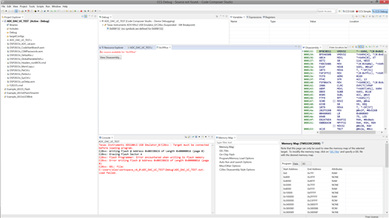
    And this is a screenshot of the CCS window:

    Thanks,

    -Alex

  • Alex,

    Could you try loading one of the RAM-based F28335 example projects from controlSUITE?

    Perhaps something like timed_led_blink? (and then perhaps flash_f28335 next if that works)  Ideally you just need to try to load the program since your issue seems to be with the loading process.


    Thank you,
    Brett

  • Hi Brett,

    Yes I have tried timed_led_blink and it does not work on my board.  I get the same error when trying to erase flash.  The project that I am trying to load is actually the Example_2833xEPwmTimerInt sample project, I only changed the name.

    -Alex

  • Ssince the last post I have redesigned the board to match very closely what is provided in the hardware design guidelines and spectrum digital schematics for the ezdsp f28335.  I have the same setup and am using the LED Blink sample project from TI, but I still encounter the same error.

    What else could be the problem?  I am baffled...