Hi
I am trying to implement current regulator using voltage source invertor. I am using PI regulator. I am proceeding in the following way
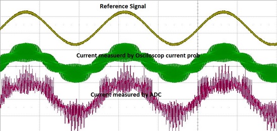
ABC to alpha beta to dq0 at dq level i am calculating error signal and implementing PI. Then this PI value is converted to ABC and generate gating signals for VSI using sine triangle PWM. But regulator dont work at all. My measured values of currents are shown in fig that shows measured signal is noisy.
I am using 10kHz carrier frequency for invertor and PWM counter counts for 7500 for each period. It means if i use 0.8 modulation index, Reference signal generated by PI should not go beyond 6000. It means I should put a limit of +3000 to -3000 on PI output to give it as a reference signal for above mentioned details. But PI get saturated only with KP = 5 and Ki = 2 and error is never minimized. As I increase the input voltage, current increases without any control just like open loop system. I am implementing current regulator for the first time so please help .
Regards
Shahid


