This thread has been locked.

If you have a related question, please click the "Ask a related question" button in the top right corner. The newly created question will be automatically linked to this question.

F28335 ADC Offset Trip (ADCOFFTRIM) too high?

Other Parts Discussed in Thread: TMS320F28335

We have been having problems with units built around a TMS320F28335, using the ADC many readings are too high.  We traced the problem to (we think) an offset, i.e. the ADC returns non-zero when connected to 0V / ground.  In three different units we have found typical readings for 0V of 19, 6, 13.

I eventually thought to look at ADCOFFTRIM, and in each case found the value there was close to the observed offset described above.  I if follow section 1.10 of the ADC Ref Guide (spru812a), the value for ADCOFFTRIM ends up at about -2.

It’s only 3 samples, but it looks like the ADC_Cal value is making things worse.  Simply setting ADCOFFTRIM to zero gives better results.

Any explanation for this?

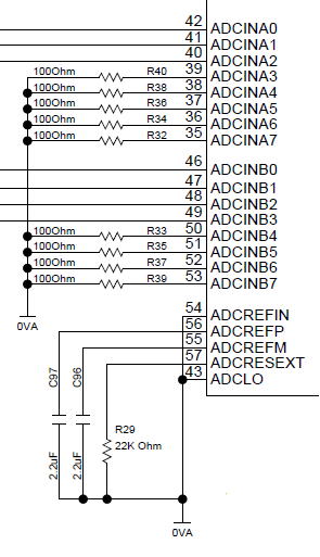
We are using the internal ADC reference, with ADCOFFTRIM, ADCRESEXT, ADCREFP, ADCREFM, ADCLO grounded.

Regards.

  • Giles,

    Consider that the ADCOFFTRIM value determined by TI at production time does not take into account your board level offsets caused by the signal conditioning signal chain you are using on your input signal (e.g., offset in your instrumentation amplifier, etc.).  Perhaps that has something to do with it.

    Regards,

    David

  • David,

    ADCOFFTRIM, ADCRESEXT, ADCREFP, ADCREFM, ADCLO plus ADC channels A4, B4, ... A7, B7 are all tied to the same ground.  When reading these channels I get readings close to ADCOFFTRIM rather than close to zero.

    Would what you suggest really cause that?  It seems to me that whatever else is going on, our setup should give zero for grounded channels.

    Regards,
    Giles

  • Hi Giles,

    What PCB is the device on?  A TI supplied EVM, or a custom application board? If a custom board, is the common ground a plane, or just a trace (the ADC can be sensitive to parasitic resistance/inductance connected to the analog grounds and reference pins)?

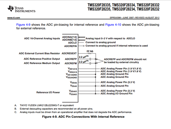
    Are you grounding REFP/REFM, or connecting them to ground via 2.2uF capacitor?  They need the capacitors even when using internal reference (they stabilize the internally generated voltage).  Same thing goes for ADCRESEXT; are you grounding it, or connecting it to ground via 22K resistor? 

    You won't always get a reading of 0 LSBs when converting ground.  We specify the offset error in the datasheet as +/-15 LSBs.  A reading of 6 LSBs when sampling ground is plausible, but I agree that 13 or 19 LSBs under nominal conditions is definitely unexpected.

    Another thing to check is the ADC clock rate.  I believe that some old F28335 ADC software examples had a bug where the clock rate was set to 75MHz instead of 25MHz, which can produce some strange results. 

  • Giles,

    Could you tell if this is a single unit showing the behavior or multiple (and how many).  As David and Devin said it could be a PCB issue or possibly an issue with this specific device.  Seeing the behaviour across boards will be instructive.

    Thanks,

    Jason

  • Devin, Jason

    We are using a custom board.  Everything is grounded to a plane.

    The various ADC-related pins are connected as in your picture, see snippet from out board schematic below.

    So far we have seen this issue with three boards.  Others we have are embedded in other equipment and so not easy to get hold of to test, though I will try.

    For our board, SYSCLKOUT = 144 MHz & FCLK = 12.0 MHz, which I hope is OK.  We are using F28335 rev A

    I have what I think is the F28335 Explorer's Kit, but this has ADCOFFTRIM = -2, so doesn't help.  Unfortunately I don't have access to any other F28335s to compare with our board.

    Our best option may be to go ahead with the recommended offset correction procedure.

    Regards,
    Giles