This thread has been locked.

If you have a related question, please click the "Ask a related question" button in the top right corner. The newly created question will be automatically linked to this question.

Cannot setup HRPWM on F28377D

Other Parts Discussed in Thread: CONTROLSUITE

Hi,

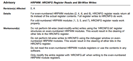
I have a problem setting up the HRPWM registers of my F28377D controller: I am using the routine prescribed on TI's wiki (see below) but the weirdest thing happens. If I step by step go through the for loop for successively initializing the HRPWM of my ePWM1, ePWM2,... ePWM10 modules then I can ONLY WRITE TO ODD ePWM modules: ePWM1.HRCFNG register will be set properly when ePWM2, ePWM4, ePMW6 will not!

I also tried to set ePWM3.HRCFNG directly and that didn't work either.

I am really puzzled...Is that a bug ?

Thanks in advance for your help,

Regards,

Francois.

Uint16 j;
// ePWM channel register configuration with HRPWM
// ePWMxA / ePWMxB toggle low/high with MEP control on Rising edge
EALLOW;
CpuSysRegs.PCLKCR0.bit.TBCLKSYNC = 0;
EDIS;

for (j=1;j<=NB_IMPEDANCE_BURST_CHANNELS;j++)
{

(*eHRPWM[j]).TBCTL.bit.PRDLD = TB_IMMEDIATE; // set Immediate load
(*eHRPWM[j]).TBPRD = PWM_5MHZ_MODULATION_PERIOD-1; // PWM frequency = 1 / period
(*eHRPWM[j]).CMPA.half.CMPA = PWM_5MHZ_MODULATION_PERIOD / 2; // set duty 50% initially
(*eHRPWM[j]).CMPA.half.CMPAHR = (1 << 8); // initialize HRPWM extension
(*eHRPWM[j]).CMPB.half.CMPB = PWM_5MHZ_MODULATION_PERIOD / 2; // set duty 50% initially
(*eHRPWM[j]).CMPB.all |= (0 << 8); // initialize HRPWM extension
(*eHRPWM[j]).TBPHS.all = 0;

(*eHRPWM[j]).TBCTR = 0;
(*eHRPWM[j]).TBCTL.bit.CTRMODE = TB_COUNT_UP;
(*eHRPWM[j]).TBCTL.bit.SYNCOSEL = TB_SYNC_DISABLE;
(*eHRPWM[j]).TBCTL.bit.HSPCLKDIV = TB_DIV1; // ePWM CLK = SYSCLOCK
(*eHRPWM[j]).TBCTL.bit.CLKDIV = TB_DIV1;
(*eHRPWM[j]).TBCTL.bit.FREE_SOFT = 11;

(*eHRPWM[j]).CMPCTL.bit.LOADAMODE = CC_CTR_ZERO;
(*eHRPWM[j]).CMPCTL.bit.LOADBMODE = CC_CTR_ZERO;
(*eHRPWM[j]).CMPCTL.bit.SHDWAMODE = CC_SHADOW;
(*eHRPWM[j]).CMPCTL.bit.SHDWBMODE = CC_SHADOW;


(*eHRPWM[j]).AQCTLA.bit.ZRO = AQ_SET; // PWM toggle high/low
(*eHRPWM[j]).AQCTLA.bit.CAU = AQ_CLEAR;
(*eHRPWM[j]).AQCTLB.bit.ZRO = AQ_SET;
(*eHRPWM[j]).AQCTLB.bit.CAU = AQ_CLEAR;

EALLOW;
(*eHRPWM[j]).HRCNFG.all = 0x0;
(*eHRPWM[j]).HRCNFG.bit.EDGMODE = HR_FEP; // MEP control on falling edge
(*eHRPWM[j]).HRCNFG.bit.CTLMODE = HR_CMP;
(*eHRPWM[j]).HRCNFG.bit.HRLOAD = HR_CTR_ZERO;
(*eHRPWM[j]).HRCNFG.bit.EDGMODEB = HR_FEP; // MEP control on falling edge
(*eHRPWM[j]).HRCNFG.bit.CTLMODEB = HR_CMP;
(*eHRPWM[j]).HRCNFG.bit.HRLOADB = HR_CTR_ZERO;
(*eHRPWM[j]).HRCNFG.bit.AUTOCONV = 1;
(*eHRPWM[j]).HRPCTL.bit.HRPE = 0; // Turn 0 high-resolution period control.
(*eHRPWM[j]).TBCTL.bit.PHSEN = TB_DISABLE;
(*eHRPWM[j]).HRPCTL.bit.TBPHSHRLOADE = 0;
EDIS;
}

  • Hi Francois,

    I hope you've referred the HRPWM example code present here:

    C:\ti\controlSUITE\device_support\F2837xD\v120\F2837xD_examples_Cpu1\hrpwm_duty_sfo_v8

    It shows the implementation of multi-HRPWM channels.

    Regards,

    Gautam

  • Moreover,

    I tried and set up the HRPWM registers from CPU2 but no luck. I tried several things including playing around with the activation sequence of the ePWM clocks, HRPWM clocks and TBSYNCCLK clock.. Does this mean that the HRPWM modules can only be controlled by CPU1 ?

    Thanks for your help.

    Kind regards,

  • Hi Gautam,

    Yes I relied on that example to write my code. No luck so far.. 

    I tried both from CPU1 and from CPU2. As I said from CPU1 I manage to configure a few of the HRPWM channels whereas from CPU2 it appears only the ePMW registers are accessible..

    That's a bummer..

    Regards,

    Francois

  • Francois Patou said:
    Does this mean that the HRPWM modules can only be controlled by CPU1 ?

    No, not at all. HRPWM can be configured from CPU2 as well. Refer page number 63 of device datasheet.

    Regards,

    Gautam

  • Francois Patou said:

    Yes I relied on that example to write my code. No luck so far.. 

    I tried both from CPU1 and from CPU2. As I said from CPU1 I manage to configure a few of the HRPWM channels whereas from CPU2 it appears only the ePMW registers are accessible..

    That's a bummer..

    That's very weird as I've tested all the basic peripheral codes and they were very well functional. Did you refer the lab 3 of the F28377D workshop? If not, please do... here is the link:

    http://software-dl.ti.com/trainingTTO/trainingTTO_public_sw/F2837xD/F2837xD%20Workshop-1.0-Setup.exe

    Regards,

    Gautam

  • Gautam,

    Yes I've checked the lab as well as the examples. I actually get the ePWM modules properly set up from CPU2 but I still cannot use the HRPWM!

    Any chance you could take a look at my code ? 

    From CPU2 none of the write operation work on the HCNFG register, even though the HRPWM clock is set and the TBSYNCCLK is cleared.

    Thanks for your help.

    Regards,

    F.

  • Francois,

    What version of silicon are you using?  Please see the errata issued for this product on the TI website:

    http://www.ti.com/lit/er/sprz412b/sprz412b.pdf

  • Hello

    I have same problems. I'm not able to setup the HRCNFG from CPU2. (errata advices implemented) The same initialization work on CPU1 but do not work on CPU2. (CPUSEL for CPU2 is set) Do you have found any solutions or further advices?

    Thanks for your help.

    best regards

    Jens
  • Hi Jens,

    Unfortunately not. I disactivate the high-resolution PWM and am using the simple ePWM instead. ePWM initialization from CPU2 works just fine.

    If you find a solution I'm interested though!

    Best regards,

    François.

  • Hi François,

    It works ! It seems to be possible to implement the HRPWM on CPU1 and CPU2. I will check it again and inform you about my technical advances.

    So long!

    Best regards
    Jens
  • Hi François,

    try to initialize the "EPwmXRegs.HRCNFG" Regs from CPU1. The other initialize code for PWM (using in CPU2) initialize on CPU2.
    I hope its a solution for you.

    It would be nice to get a feedback.

    good luck!

    Best regards
    Jens
  • Jens,

    I can confirm that it looks like HRCNFG.all cannot be accessed from CPU2. I made a test (Silicon A) with ePWM1, controlled by CPU1, and ePWM5, controlled by CPU2.  

    • Both ePWM1 and ePWM5 are initialized to HR-control on falling edges.
    • ePWM1 is initialized in HR-mode by CPU1 (fully working, no problems).
    • ePWM5 is initialized in HR-mode by CPU2, after control for ePWM5 has beed passed over from CPU1 to CPU2 (CPUSEL0).
    • If ePWM5-HRCNFG is initilized by CPU2, HR-mode is not working. If ePWM5-HRCNFG is  initialized by CPU1, before ePWM5 is handed over to CPU2 (CPUSEL0) and the rest of ePWM5 is initialized later  by CPU2, HR is  working as expected.

    Would be nice to get a comment on that from TI...

    Frank

  • Hi Frank,

    I can confirm that this is the how the chip is deisgned.  All HRPWM configuration must be performed from CPU1.  This is a similar methodology to many things on the chips such as configuring GPIOs.  Run time registers which affect the HRPWM output can be modified from whichever CPU has control of the corresponding EPWM module.

    Please let me know if there are any further details I can provide.

    Kris

  • Kris,

    thanks for the confirmation. Can you please point out the corresponding docs? I did not find this information both in TRM nor Datasheet. Is there a table of "CPU1 - only accessible registers"?

    Thanks

    Frank

  • Hi Frank.

    Very old thread...I know...

    I did find the information in the current datamanual. Figure 1-1 Functional Block Diagram shows HRPWM on CPU1 only.

    The current TRM is lacking this information. I will submit a bug against the TRM so it will be updated.

    Regards,
    Lori