This thread has been locked.

If you have a related question, please click the "Ask a related question" button in the top right corner. The newly created question will be automatically linked to this question.

Reading data from SCIRXBUF to a variable

Hi 

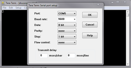
I want to read the data from SCIRXBUF and transfer it to a variable so as to extract the value which is being transmitted bit by bit from my transmission module.

This is wat i am trying to do

int factor = 10000;
int number = 0;

both these defined as global variables.

do

{
factor = factor / 10;
while(ScibRegs.SCIFFRX.bit.RXFFST !=1) { } // wait for RXDY =1 for empty state,i.e until FIFO has one word

// Get character
a = ScibRegs.SCIRXBUF.all;
number = number + (a * factor);

}while(factor>=1)

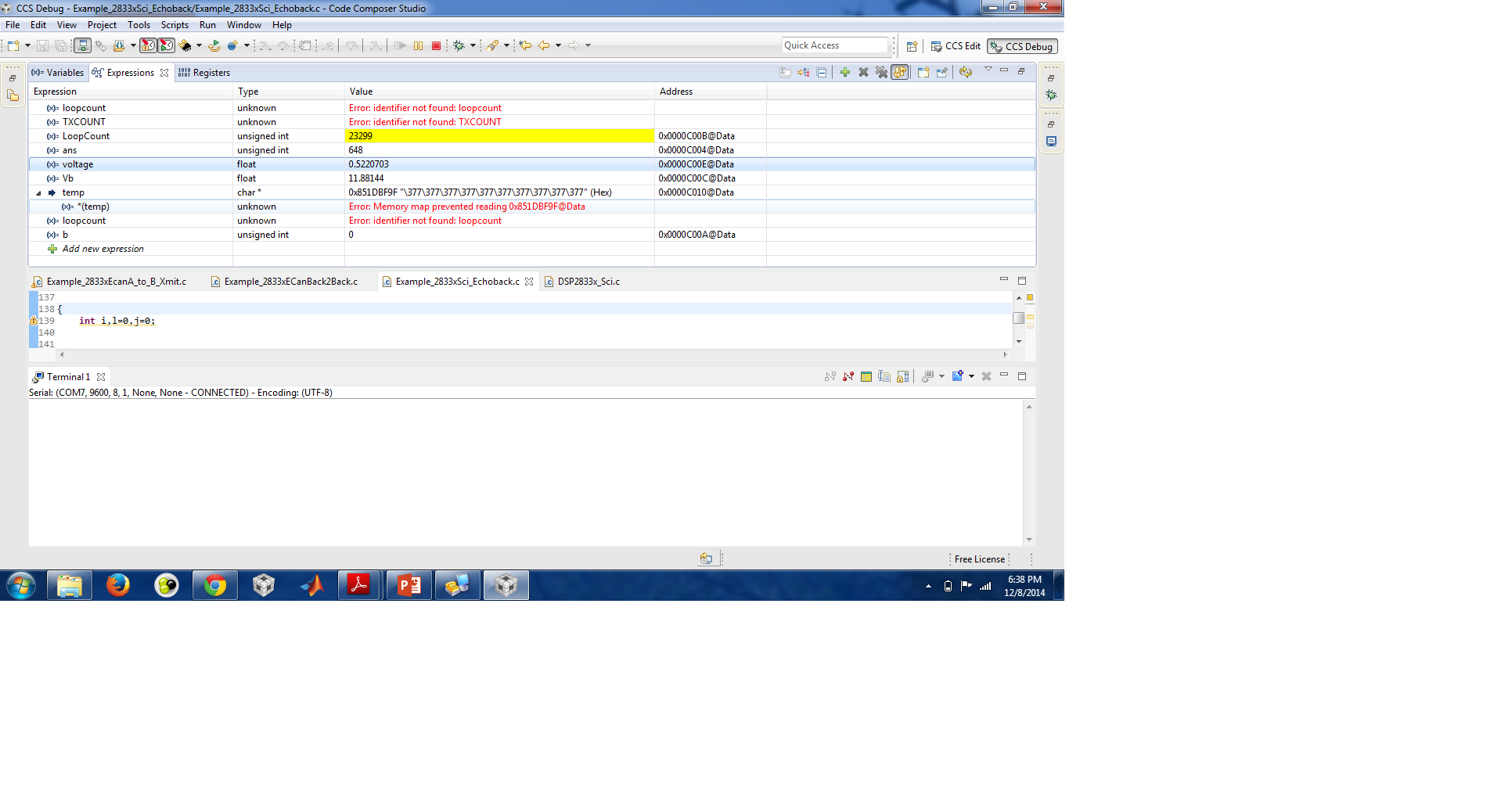
But when I check the variables on watch window..Factor=10000,number = 0,a =unidentified

please help

thanks

Sneha

  • Sneha,

    Have you halted the processor after running to see where it is in the code?  If it is stuck at the first while loop, then you are not receiving any data.  There are some good starting examples in Control Suite for SCI(echoing back with Hyperterm), use those to debug to make sure your SCI is receiving; then you can add the code around it.

  • HI

    The code is working and exceeds the first while loop.I am able to extract the number from bits of RxBuf but they give me correct number only when Tx and Rx are started together.

    the following is the latest thread in this regard:

    http://e2e.ti.com/support/microcontrollers/c2000/f/171/t/381621.aspx

    How can i add some recognition bit or flag bit with the bits being transferred.?

    Thanks

    Sneha

  • Hello Sneha,

    How about using interrupt?
    Have you tried it?

    Best regards,

    Maria

  • Hi Maria

    Yes I am usinq interrupts using ISR available with it.

    Thanks

    Sneha

  • Hey maria

    The problem is resolved.

    I had to transfer some flag bits with the data for its accurate extraction at reciever end.Theprogram is working just perfect.

    Thanks

    Sneha

  • Great to know! Good luck!

    Best regards,

    Maria

  • Hi

    Can someone help me out with the display of this data on the hyperterminal?

    Thanks and regards

    Sneha

  • Hello Sneha,

    You said your SCI code already worked prefectly.

    What is the problem now? Can you be more specific?

    Do you want to transfer the data to Hyperterminal now?

    Best regards,

    Maria

  • Hi Maria

    Thanks for the reply

    Yes my SCI mode is working perfectly.Below I am sharing the code.

    Tx:

    1055.28069tx-ADC TO SCI FINAL.txt
    // TI File $Revision: /main/2 $
    // Checkin $Date: January 4, 2011   10:03:22 $
    //###########################################################################
    //
    // FILE:    Example_2806xSci_Echoback.c
    //
    // TITLE:   F2806x Device SCI Echoback.
    //
    // ASSUMPTIONS:
    //
    //    This program requires the F2806x header files.
    //    As supplied, this project is configured for "boot to SARAM" operation.
    //
    //    Connect the SCI-A port to a PC via a transciever and cable.
    //    The PC application 'hypterterminal' can be used to view the data
    //    from the SCI and to send information to the SCI.  Characters recieved
    //    by the SCI port are sent back to the host.
    //
    //    As supplied, this project is configured for "boot to SARAM"
    //    operation.  The F2806x Boot Mode table is shown below.
    //    $Boot_Table:
    //
    //    While an emulator is connected to your device, the TRSTn pin = 1,
    //    which sets the device into EMU_BOOT boot mode. In this mode, the
    //    peripheral boot modes are as follows:
    //
    //      Boot Mode:       EMU_KEY        EMU_BMODE
    //                       (0xD00)         (0xD01)
    //      ---------------------------------------
    //      Wait             !=0x55AA        X
    //      I/O              0x55AA          0x0000
    //      SCI              0x55AA          0x0001
    //      Wait             0x55AA          0x0002z
    //      Get_Mode         0x55AA          0x0003
    //      SPI              0x55AA          0x0004
    //      I2C              0x55AA          0x0005
    //      OTP              0x55AA          0x0006
    //      ECANA            0x55AA          0x0007
    //      SARAM            0x55AA          0x000A   <-- "Boot to SARAM"
    //      Flash            0x55AA          0x000B
    //      Wait             0x55AA          Other
    //
    //   Write EMU_KEY to 0xD00 and EMU_BMODE to 0xD01 via the debugger
    //   according to the Boot Mode Table above. Build/Load project,
    //   Reset the device, and Run example
    //
    //   $End_Boot_Table
    //
    //
    // Description:
    //
    //
    //    This test recieves and echo-backs data through the SCI-A port.
    //
    //    1) Configure hyperterminal:
    //       Use the included hyperterminal configuration file SCI_96.ht.
    //       To load this configuration in hyperterminal: file->open
    //       and then select the SCI_96.ht file.
    //    2) Check the COM port.
    //       The configuration file is currently setup for COM1.
    //       If this is not correct, disconnect Call->Disconnect
    //       Open the File-Properties dialog and select the correct COM port.
    //    3) Connect hyperterminal Call->Call
    //       and then start the F2806x SCI echoback program execution.
    //    4) The program will print out a greeting and then ask you to
    //       enter a character which it will echo back to hyperterminal.
    //
    //
    //    Watch Variables:
    //       LoopCount for the number of characters sent
    //       ErrorCount
    //
    //
    //###########################################################################
    // $TI Release: 2806x C/C++ Header Files and Peripheral Examples V1.00 $
    // $Release Date: January 11, 2011 $
    //###########################################################################
    
    #include "DSP28x_Project.h"     // Device Headerfile and Examples Include File
    
    
    // Prototype statements for functions found within this file.
    void scia_echoback_init(void);
    void scia_fifo_init(void);
    void scia_xmit(int a);
    void error();
    
    interrupt void adc_isr(void);
    interrupt void scia_tx_isr(void);
    void Adc_Config(void);
    void send_result(int res);
    
    // Global counts used in this example
    Uint16 LoopCount;
    Uint16 Voltage1;
    //Uint16 Voltage2;
    Uint16 LoopCount1;
    Uint16 ErrorCount;
    float b;
    float V1,Va;
    int i,b3=0,b2=0,b1=0,b0;
    int B3 = 0x40,B2=0x30,B1=0x20,B0=0x10; // defining flag bits for accurate transfer
    
    void main(void)
             {
        Uint16 SendChar;
    //  int ReceivedChar;
      //  char *msg;
    
    // Step 1. Initialize System Control:
    // PLL, WatchDog, enable Peripheral Clocks
    // This example function is found in the F2806x_SysCtrl.c file.
       InitSysCtrl();
    
    // Step 2. Initalize GPIO:
    // This example function is found in the F2806x_Gpio.c file and
    // illustrates how to set the GPIO to it's default state.
       // InitGpio(); Skipped for this example
    
    // For this example, only init the pins for the SCI-A port.
    // This function is found in the F2806x_Sci.c file.
       InitSciaGpio();
    
    // Step 3. Clear all interrupts and initialize PIE vector table:
    // Disable CPU interrupts
       DINT;
    
    // Initialize PIE control registers to their default state.
    // The default state is all PIE interrupts disabled and flags
    // are cleared.
    // This function is found in the F2806x_PieCtrl.c file.
       InitPieCtrl();
    
    // Disable CPU interrupts and clear all CPU interrupt flags:
       IER = 0x0000;
       IFR = 0x0000;
    
    // Initialize the PIE vector table with pointers to the shell Interrupt
    // Service Routines (ISR).
    // This will populate the entire table, even if the interrupt
    // is not used in this example.  This is useful for debug purposes.
    // The shell ISR routines are found in F2806x_DefaultIsr.c.
    // This function is found in F2806x_PieVect.c.
       InitPieVectTable();
       EALLOW;
       PieVectTable.ADCINT1 = &adc_isr;
       EDIS;
       
      
    // Step 4. Initialize all the Device Peripherals:
    // This function is found in F2806x_InitPeripherals.c
    // InitPeripherals(); // Not required for this example
       scia_fifo_init();       // Initialize the SCI FIFO
         scia_echoback_init();  // Initalize SCI for echoback
       InitAdc();
    
    EnableInterrupts();
    // Step 5. User specific code:
       //Enable ADCINT1 in PIE
       PieCtrlRegs.PIEIER1.bit.INTx1 = 1;
       IER |= M_INT1;
       EINT;
       ERTM;
    b=0;
        LoopCount = 0;
        LoopCount1 = 0;
        ErrorCount = 0;
    
     //Configure ADC
                EALLOW;
            AdcRegs.ADCCTL2.bit.ADCNONOVERLAP = 1;  // Enable non-overlap mode
            AdcRegs.ADCCTL1.bit.INTPULSEPOS = 1;    //ADCINT1 trips after AdcResults latch
            AdcRegs.INTSEL1N2.bit.INT1E     = 1;    //Enabled ADCINT1
            AdcRegs.INTSEL1N2.bit.INT1CONT  = 0;    //Disable ADCINT1 Continuous mode
            AdcRegs.INTSEL1N2.bit.INT1SEL   = 1;    // setup EOC1 to trigger ADCINT1 to fire
            AdcRegs.ADCSOC0CTL.bit.CHSEL    = 4;    // set SOC0 channel select to ADCINA4
            AdcRegs.ADCSOC1CTL.bit.CHSEL    = 2;    // set SOC1 channel select to ADCINA2
            AdcRegs.ADCSOC0CTL.bit.TRIGSEL  = 5;    // set SOC0 start trigger on EPWM1A, due to round-robin SOC0 converts first then SOC1
            AdcRegs.ADCSOC1CTL.bit.TRIGSEL  = 5;    // set SOC1 start trigger on EPWM1A, due to round-robin SOC0 converts first then SOC1
            AdcRegs.ADCSOC0CTL.bit.ACQPS    = 6;    //set SOC0 S/H Window to 7 ADC Clock Cycles, (6 ACQPS plus 1)
            AdcRegs.ADCSOC1CTL.bit.ACQPS    = 6;    //set SOC1 S/H Window to 7 ADC Clock Cycles, (6 ACQPS plus 1)
            EDIS;
    
        // Assumes ePWM1 clock is already enabled in InitSysCtrl();
           EPwm1Regs.ETSEL.bit.SOCAEN   = 1;        // Enable SOC on A group
           EPwm1Regs.ETSEL.bit.SOCASEL  = 4;        // Select SOC from CMPA on upcount
           EPwm1Regs.ETPS.bit.SOCAPRD   = 1;        // Generate pulse on 1st event
           EPwm1Regs.CMPA.half.CMPA     = 0x0080;   // Set compare A value
           EPwm1Regs.TBPRD              = 0xFFFF;   // Set period for ePWM1
           EPwm1Regs.TBCTL.bit.CTRMODE  = 0;        // count up and start
    
        // Wait for ADC interrupt
    
           SendChar = 0;
           for(i=0;i<50;i++)
          {
           LoopCount++;
            
           send_result(Voltage1); //send to extract bits
        
            //break;
          }
    
     
    }
    
    interrupt void  adc_isr(void)
    {
    
      Voltage1 = AdcResult.ADCRESULT0; //decimal value
      //send_result(Voltage1);
      V1 = Voltage1;
      Va = (V1 * 3.3)/(4095); //extracting analog value
      //Voltage2 = AdcResult.ADCRESULT1;
    b=5;
        AdcRegs.ADCINTFLGCLR.bit.ADCINT1 = 1;       //Clear ADCINT1 flag reinitialize for next SOC
      PieCtrlRegs.PIEACK.all = PIEACK_GROUP1;   // Acknowledge interrupt to PIE
     return;
    }
    // Test 1,SCIA  DLB, 8-bit word, baud rate 0x000F, default, 1 STOP bit, no parity
    void scia_echoback_init()
    {
        // Note: Clocks were turned on to the SCIA peripheral
        // in the InitSysCtrl() function
    
        SciaRegs.SCICCR.all =0x0007;   // 1 stop bit,  No loopback
                                       // No parity,8 char bits,
                                       // async mode, idle-line protocol
        SciaRegs.SCICTL1.all =0x0002;  // enable TX, RX, internal SCICLK,0003
                                       // Disable RX ERR, SLEEP, TXWAKE
        SciaRegs.SCICTL2.all =0x0001;//0003
        SciaRegs.SCICTL2.bit.TXINTENA =1;
        //SciaRegs.SCICTL2.bit.RXBKINTENA =1;
    
        SciaRegs.SCIHBAUD    =0x01;  // 9600 baud @LSPCLK = 20MHz (80 MHz SYSCLK).
        SciaRegs.SCILBAUD    =0x03;
    
        SciaRegs.SCICTL1.all =0x0022;  // Relinquish SCI from Reset0023
    }
    
    // Transmit a character from the SCI
    void scia_xmit(int a)
    {
        while (SciaRegs.SCIFFTX.bit.TXFFST != 0) {}
        //SciaRegs.SCICTL1.all =0x0022;
        SciaRegs.SCITXBUF=a;
        b=6;
    
    }


    // Initalize the SCI FIFO
    void scia_fifo_init()
    {
        SciaRegs.SCIFFTX.all=0xE040;
      //  SciaRegs.SCIFFRX.all=0x2044;
        SciaRegs.SCIFFCT.all=0x0;
    
    }
    
    void send_result(int res)
    {
    
     b3 = (res/1000);
     b2 = ((res%1000)/100);
     b1 = ((res%100)/10);
     b0 = (res%10);
    b3 = b3 + B3;
    b2 = b2 + B2;
    b1 = b1 + B1;
    b0 = b0 + B0;
     DELAY_US(1000000);
     scia_xmit(b3);
     DELAY_US(1000000);
    scia_xmit(b2);
    DELAY_US(1000000);
    scia_xmit(b1);
    DELAY_US(1000000);
    scia_xmit(b0);
    DELAY_US(1000000);
    
     return;
    }
    
    //===========================================================================
    // No more.
    //===========================================================================


    Rx:

    2843.28335-rx adc to sci final.txt
    // TI File $Revision: /main/2 $
    // Checkin $Date: July 30, 2009   18:45:31 $
    //###########################################################################
    //// FILE:    Example_2833xSci_Echoback.c
    //
    // TITLE:   DSP2833x Device SCI Echoback.
    //
    // ASSUMPTIONS:
    //
    //    This program requires the DSP2833x header files.
    //    As supplied, this project is configured for "boot to SARAM" operation.
    //
    //    Connect the SCI-A port to a PC via a transciever and cable.
    //    The PC application 'hypterterminal' can be used to view the data
    //    from the SCI and to send information to the SCI.  Characters recieved
    //    by the SCI port are sent back to the host.
    //
    //    As supplied, this project is configured for "boot to SARAM"
    //    operation.  The 2833x Boot Mode table is shown below.
    //    For information on configuring the boot mode of an eZdsp,
    
    //    please refer to the documentation included with the eZdsp,
    //       $Boot_Table:
    //
    //         GPIO87   GPIO86     GPIO85   GPIO84
    //          XA15     XA14       XA13     XA12
    //           PU       PU         PU       PU
    //        ==========================================
    //            1        1          1        1    Jump to Flash
    
    //            1        1          1        0    SCI-A boot
    
    //            1        1          0        1    SPI-A boot
    
    //            1        1          0        0    I2C-A boot
    
    
    //            1        0          1        1    eCAN-A boot
    //            1        0          1        0    McBSP-A boot
    
    //            1        0          0        1    Jump to XINTF x16
    
    //            1        0          0        0    Jump to XINTF x32
    //            0        1          1        1    Jump to OTP
    
    //            0        1          1        0    Parallel GPIO I/O boot
    
    //            0        1          0        1    Parallel XINTF boot
    
    
    //            0        1          0        0    Jump to SARAM       <- "boot to SARAM"
    
    //            0        0          1        1    Branch to check boot mode
    
    
    //            0        0          1        0    Boot to flash, bypass ADC cal
    
    
    //            0        0          0        1    Boot to SARAM, bypass ADC cal
    
    //            0        0          0        0    Boot to SCI-A, bypass ADC cal
    
    //                                              Boot_Table_End$
    //
    // DESCRIPTION:
    //
    //
    
    //    This test recieves and echo-backs data through the SCI-A port.
    //
    
    //    1) Configure hyperterminal:
    
    //       Use the included hyperterminal configuration file SCI_96.ht.
    //       To load this configuration in hyperterminal: file->open
    
    //       and then select the SCI_96.ht file.
    
    //    2) Check the COM port.
    
    //       The configuration file is currently setup for COM1.
    
    //       If this is not correct, disconnect Call->Disconnect
    //       Open the File-Properties dialog and select the correct COM port.
    
    //    3) Connect hyperterminal Call->Call
    //       and then start the 2833x SCI echoback program execution.
    
    //    4) The program will print out a greeting and then ask you to
    
    //       enter a character which it will echo back to hyperterminal.
    
    
    //
    
    //    As is, the program configures SCI-A for 9600 baud with
    
    
    //    SYSCLKOUT = 150MHz and LSPCLK = 37.5 MHz
    //    SYSCLKOUT = 100MHz and LSPCLK = 25.0 Mhz
    
    //
    
    //
    //    Watch Variables:
    
    //       LoopCount for the number of characters sent
    
    //       ErrorCount
    
    //###########################################################################
    // $TI Release: 2833x/2823x Header Files V1.32 $
    // $Release Date: June 28, 2010 $
    //###########################################################################
    #include "DSP28x_Project.h"     // Device Headerfile and Examples Include File
    // Prototype statements for functions found within this file.
    void scib_echoback_init(void);
    void scib_fifo_init(void);
    interrupt void scib_rx_isr(void);
    
    //Global counts used in this example
    Uint16 LoopCount;
    Uint16 ErrorCount;
    Uint16 b,c,d,e,f,g,h, ans;
    volatile Uint16 a=0;
    //Uint16 factor;
    float voltage;
    Uint16 number=0x0;
    void main(void)
    
    {
        int i;
    
    
       // Step 1. Initialize System Control:
     // PLL, WatchDog, enable Peripheral Clocks
    
        // This example function is found in the DSP2833x_SysCtrl.c file.
    
    
       InitSysCtrl();
    
    
      // Step 2. Initalize GPIO:


        // This example function is found in the DSP2833x_Gpio.c file and
    
        // illustrates how to set the GPIO to it's default state.
    
       // InitGpio(); Skipped for this example
    
    // For this example, only init the pins for the SCI-A port.
    
     // This function is found in the DSP2833x_Sci.c file.
    
      InitScibGpio();
    //Step 3. Clear all interrupts and initialize PIE vector table:
     // Disable CPU interrupts
     DINT;
    // Initialize PIE control registers to their default state.
      // The default state is all PIE interrupts disabled and flags
    
       // are cleared.
     // This function is found in the DSP2833x_PieCtrl.c file.
     InitPieCtrl();
     // Disable CPU interrupts and clear all CPU interrupt flags:
      IER = 0x0000;
       IFR = 0x0000;
     // Initialize the PIE vector table with pointers to the shell Interrupt
     // Service Routines (ISR).
        // This will populate the entire table, even if the interrupt
     // is not used in this example.  This is useful for debug purposes.
     // The shell ISR routines are found in DSP2833x_DefaultIsr.c.
    // This function is found in DSP2833x_PieVect.c.
      InitPieVectTable();
       // Step 4. Initialize all the Device Peripherals:
       // This function is found in DSP2833x_InitPeripherals.c
     // InitPeripherals(); // Not required for this example
     EnableInterrupts();
      // Step 5. User specific code:
    
     LoopCount = 0;
    
     ErrorCount = 0;
       // factor = 0x2710;
    
      scib_fifo_init();      // Initialize the SCI FIFO
      scib_echoback_init();  // Initalize SCI for echoback
    
      for(;;)
    
       {
    
        // Wait for inc character
    
           while(ScibRegs.SCIFFRX.bit.RXFFST !=0) { } // wait for RXDY =1 for empty state,i.e until FIFO has one word
           DELAY_US(1000000);
    
        a = ScibRegs.SCIRXBUF.all;
           // Get character
        if (a != '\0') // wait till transmission starts ,note that null condition will stand true even
                      //if voltage data sends zero,to avoid that the flag bits being sent are other then zero
    
        {
             d=a & 0x70; // extracts the flag bitset at the tranciever to identify the bit(MSB/LSB)
    
            c=a & 0x0F; // extracts the actual databit
    
        if(d==0x40)  // MSB i.e. bit b3
        {
            e=c*0x03E8;
        }
        if(d==0x30)  //bit b2
        {
            f=c*0x64;
        }
        if(d==0x20) //bit b1
        {
            g=c*0xA;
        }
        if(d==0x10) //bit b0
        {
            h=c*0x01;
        }
        ans=e+f+g+h;
    
    
               //factor = factor / 0xA;
               //number = number + a * factor;
        voltage = (ans * 3.3)/4095;
    
            LoopCount++;
      //   if(factor < 0x1)
        // {
          //  factor = 0x2710;
          // number = 0x0;
        // }
        }
    
        }
    }
    
    // Test 1,SCIA  DLB, 8-bit word, baud rate 0x000F, default, 1 STOP bit, no parity
    void scib_echoback_init()
       // Note: Clocks were turned on to the SCIA peripheral // in the InitSysCtrl() function
    {
       ScibRegs.SCICCR.all =0x0007;   // 1 stop bit,  No loopback
                                        // No parity,8 char bits,
                                            // async mode, idle-line protocol
      ScibRegs.SCICTL1.all =0x0001;  // disable TX, enable RX, internal SCICLK,(earlier 0003 correct one)
                                      // Disable RX ERR, SLEEP, TXWAKE
      ScibRegs.SCICTL2.all =0x0002;    // initially the correct oneis 0003
                                          //ScibRegs.SCICTL2.bit.TXINTENA =1;
       ScibRegs.SCICTL2.bit.RXBKINTENA =1;
    
    #if (CPU_FRQ_150MHZ)
       ScibRegs.SCIHBAUD    =0x0001;  // 9600 baud @LSPCLK = 37.5MHz.
       ScibRegs.SCILBAUD    =0x00E7;
    #endif
    #if (CPU_FRQ_100MHZ)
        ScibRegs.SCIHBAUD    =0x0001;  // 9600 baud @LSPCLK = 20MHz.
        ScibRegs.SCILBAUD    =0x0044;
    #endif
    
    
        ScibRegs.SCICTL1.all =0x0021;  // Relinquish SCI from Reset(initially 0023)
    
    }
    
    
    // Transmit a character from the SCI
    
    // Initalize the SCI FIFO
    
    void scib_fifo_init()
    {
        // ScibRegs.SCIFFTX.all=0xE040;
    
       ScibRegs.SCIFFRX.all=0x204f;
       ScibRegs.SCIFFCT.all=0x0;
    
    }
    

    Now I want to see this data on the hyperterminal.When I try to see I get some random symbols.

    Thanks & Regards

    Sneha

  • Sneha Thakur said:
    Now I want to see this data on the hyperterminal.When I try to see I get some random symbols.

    Try using this hyperterminal configuration file: 7444.SCI_96.zip

    Regards,

    Gautam

  • Hi Gautam

    I tried running this host file with the following reciever code:

    8738.rx 28335.txt
    // TI File $Revision: /main/2 $
    // Checkin $Date: July 30, 2009   18:45:31 $
    //###########################################################################
    //// FILE:    Example_2833xSci_Echoback.c
    //
    // TITLE:   DSP2833x Device SCI Echoback.
    //
    // ASSUMPTIONS:
    //
    //    This program requires the DSP2833x header files.
    //    As supplied, this project is configured for "boot to SARAM" operation.
    //
    //    Connect the SCI-A port to a PC via a transciever and cable.
    //    The PC application 'hypterterminal' can be used to view the data
    //    from the SCI and to send information to the SCI.  Characters recieved
    //    by the SCI port are sent back to the host.
    //
    //    As supplied, this project is configured for "boot to SARAM"
    //    operation.  The 2833x Boot Mode table is shown below.
    //    For information on configuring the boot mode of an eZdsp,
    
    //    please refer to the documentation included with the eZdsp,
    //       $Boot_Table:
    //
    //         GPIO87   GPIO86     GPIO85   GPIO84
    //          XA15     XA14       XA13     XA12
    //           PU       PU         PU       PU
    //        ==========================================
    //            1        1          1        1    Jump to Flash
    
    //            1        1          1        0    SCI-A boot
    
    //            1        1          0        1    SPI-A boot
    
    //            1        1          0        0    I2C-A boot
    
    
    //            1        0          1        1    eCAN-A boot
    //            1        0          1        0    McBSP-A boot
    
    //            1        0          0        1    Jump to XINTF x16
    
    //            1        0          0        0    Jump to XINTF x32
    //            0        1          1        1    Jump to OTP
    
    //            0        1          1        0    Parallel GPIO I/O boot
    
    //            0        1          0        1    Parallel XINTF boot
    
    
    //            0        1          0        0    Jump to SARAM       <- "boot to SARAM"
    
    //            0        0          1        1    Branch to check boot mode
    
    
    //            0        0          1        0    Boot to flash, bypass ADC cal
    
    
    //            0        0          0        1    Boot to SARAM, bypass ADC cal
    
    //            0        0          0        0    Boot to SCI-A, bypass ADC cal
    
    //                                              Boot_Table_End$
    //
    // DESCRIPTION:
    //
    //
    
    //    This test recieves and echo-backs data through the SCI-A port.
    //
    
    //    1) Configure hyperterminal:
    
    //       Use the included hyperterminal configuration file SCI_96.ht.
    //       To load this configuration in hyperterminal: file->open
    
    //       and then select the SCI_96.ht file.
    
    //    2) Check the COM port.
    
    //       The configuration file is currently setup for COM1.
    
    //       If this is not correct, disconnect Call->Disconnect
    //       Open the File-Properties dialog and select the correct COM port.
    
    //    3) Connect hyperterminal Call->Call
    //       and then start the 2833x SCI echoback program execution.
    
    //    4) The program will print out a greeting and then ask you to
    
    //       enter a character which it will echo back to hyperterminal.
    
    
    //
    
    //    As is, the program configures SCI-A for 9600 baud with
    
    
    //    SYSCLKOUT = 150MHz and LSPCLK = 37.5 MHz
    //    SYSCLKOUT = 100MHz and LSPCLK = 25.0 Mhz
    
    //
    
    //
    //    Watch Variables:
    
    //       LoopCount for the number of characters sent
    
    //       ErrorCount
    
    //###########################################################################
    // $TI Release: 2833x/2823x Header Files V1.32 $
    // $Release Date: June 28, 2010 $
    //###########################################################################
    #include "DSP28x_Project.h"     // Device Headerfile and Examples Include File
    // Prototype statements for functions found within this file.
    void scib_echoback_init(void);
    void scib_fifo_init(void);
    interrupt void scib_rx_isr(void);
    void scib_msg(char *msg);
    void scib_xmit(int a);
    
    //Global counts used in this example
    Uint16 LoopCount;
    Uint16 ErrorCount;
    Uint16 b,c,d,e,f,g,h,j=0, ans;
    volatile Uint16 a=0;
    //Uint16 factor;
    float voltage,Vb;
    float v[50];
    Uint16 number=0x0;
    void main(void)
    
    {
        int i,l=0,j=0;
        char *msg;
    
       // Step 1. Initialize System Control:
     // PLL, WatchDog, enable Peripheral Clocks
    
        // This example function is found in the DSP2833x_SysCtrl.c file.
    
    
       InitSysCtrl();
    
    
      // Step 2. Initalize GPIO:


        // This example function is found in the DSP2833x_Gpio.c file and
    
        // illustrates how to set the GPIO to it's default state.
    
       // InitGpio(); Skipped for this example
    
    // For this example, only init the pins for the SCI-A port.
    
     // This function is found in the DSP2833x_Sci.c file.
    
      InitScibGpio();
    //Step 3. Clear all interrupts and initialize PIE vector table:
     // Disable CPU interrupts
     DINT;
    // Initialize PIE control registers to their default state.
      // The default state is all PIE interrupts disabled and flags
    
       // are cleared.
     // This function is found in the DSP2833x_PieCtrl.c file.
     InitPieCtrl();
     // Disable CPU interrupts and clear all CPU interrupt flags:
      IER = 0x0000;
       IFR = 0x0000;
     // Initialize the PIE vector table with pointers to the shell Interrupt
     // Service Routines (ISR).
        // This will populate the entire table, even if the interrupt
     // is not used in this example.  This is useful for debug purposes.
     // The shell ISR routines are found in DSP2833x_DefaultIsr.c.
    // This function is found in DSP2833x_PieVect.c.
      InitPieVectTable();
       // Step 4. Initialize all the Device Peripherals:
       // This function is found in DSP2833x_InitPeripherals.c
     // InitPeripherals(); // Not required for this example
     EnableInterrupts();
      // Step 5. User specific code:
    
     LoopCount = 0;
    
     ErrorCount = 0;
       // factor = 0x2710;
    
      scib_fifo_init();      // Initialize the SCI FIFO
      scib_echoback_init();  // Initalize SCI for echoback
      msg = "\nNew Data:";
    
      for(;;)
    
       {
          scib_msg(msg);
        // Wait for inc character
           while(ScibRegs.SCIFFRX.bit.RXFFST !=0) { } // wait for RXDY =1 for empty state,i.e until FIFO has one word
           //DELAY_US(1000000);
        a = ScibRegs.SCIRXBUF.all;
           // Get character
        if (a != '\0') // wait till transmission starts ,note that null condition will stand true even
                      //if voltage data sends zero,to avoid that the flag bits being sent are other then zero
        {
    
         d=a & 0x70; // extracts the flag bitset at the tranciever to identify the bit(MSB/LSB)
    
            c=a & 0x0F; // extracts the actual databit
    
        if(d==0x40)  // MSB i.e. bit b3
        {
            e=c*0x03E8;
            l++;
        }
        if(d==0x30)  //bit b2
        {
            f=c*0x64;
            l++;
        }
        if(d==0x20) //bit b1
        {
            g=c*0xA;
            l++;
        }
        if(d==0x10) //bit b0
        {
            h=c*0x01;
            l++;
        }
        ans=e+f+g+h;
      if(l==4)
      {
    
        voltage = (ans * 3.3)/4096;
        Vb = voltage/0.04324;
        if(j<51)
        {
        v[j]= Vb;
        j++;
        }
        else
        {
            j=0;
            v[j]= Vb;
            j++;
        }
        l=0;
    
     }
            LoopCount++;
    
        }
    
        }
    }
    
    // Test 1,SCIA  DLB, 8-bit word, baud rate 0x000F, default, 1 STOP bit, no parity
    void scib_echoback_init()
       // Note: Clocks were turned on to the SCIA peripheral // in the InitSysCtrl() function
    {
       ScibRegs.SCICCR.all =0x0007;   // 1 stop bit,  No loopback
                                        // No parity,8 char bits,
                                            // async mode, idle-line protocol
      ScibRegs.SCICTL1.all =0x0001;  // disable TX, enable RX, internal SCICLK,(earlier 0003 correct one)
                                      // Disable RX ERR, SLEEP, TXWAKE
      ScibRegs.SCICTL2.all =0x0002;    // initially the correct oneis 0003
                                          //ScibRegs.SCICTL2.bit.TXINTENA =1;
       ScibRegs.SCICTL2.bit.RXBKINTENA =1;
    
    #if (CPU_FRQ_150MHZ)
       ScibRegs.SCIHBAUD    =0x0001;  // 9600 baud @LSPCLK = 37.5MHz.
       ScibRegs.SCILBAUD    =0x00E7;
    #endif
    #if (CPU_FRQ_100MHZ)
        ScibRegs.SCIHBAUD    =0x0001;  // 9600 baud @LSPCLK = 20MHz.
        ScibRegs.SCILBAUD    =0x0044;
    #endif
    
    
        ScibRegs.SCICTL1.all =0x0021;  // Relinquish SCI from Reset(initially 0023)
    
    }
    
    
    // Transmit a character from the SCI
    void scib_xmit(int a)
    {
       while (ScibRegs.SCIFFTX.bit.TXFFST != 0) {}
         ScibRegs.SCITXBUF=a;
    }
    // Initalize the SCI FIFO
    void scib_msg(char *msg)
    {
        int i=0;
        while(msg[i] != '\0')
        {
            scib_xmit(msg[i]);
            i++;
        }
    }
    void scib_fifo_init()
    {
        // ScibRegs.SCIFFTX.all=0xE040;
    
       ScibRegs.SCIFFRX.all=0x204f;
       ScibRegs.SCIFFCT.all=0x0;
    
    }
    

    But it resulted in blank hyperterminal screen.

    Please point out to what I am missing.

    * I am facing problems accessing TI website.:(

    Thanks

    sneha

  • Hi

    How do we use Printf with CCS V.6 for F28335?

    Thanks & Regards

    Sneha

  • Hi

    Thanks for the reply.

    I am reading the same link provided by you.but still I get errors

    1. erroor linking the file.

    2.

    thanks

    sneha

  • Hi 

    Any suggestions for handling the above problem.

    I have tried using sprintf command too as given in the article shared above.But to no help.Still the same error exists.

    Is this .text error related to memory allocation and sections allocation.

    Any help would be appreciated.

    Thanks

    Sneha

  • Hi

    Please suggest me the solution to get the data on the hyperterminal.

    Thanks

    Sneha

  • Hello Sneha,

    Which one that you want to see, the F28069 to PC, or F28335 to PC?

    In my opinion, you want to see the data from F28069 to PC, right?

    Do you want to see the data while F28069 still connected to F28335?

    Best regards,

    Maria

  • Hi Maria

    My connections are as follows:

    F28069 - Transmitter,senses voltage through ADC and transmits the same through SCI

    F28335 - Receiver,receives the voltage through SCI

    DIsplay- Now I want to display this Voltage from F28335 to hyperterminal....

    Thanks and Regards

    Sneha

  • Sneha,

    Can you provide more information on the build error you are seeing? It would be helpful to see the console output where the error shows up.

    If you have an open SCI port on F28335 you can connect this to Hyperterminal for the Display portion of your program. I am working on something where I transmit a counter to a terminal program running on my PC.

    I have not actually gotten anything running with Hyperterminal, but I do know that it is possilbe. I have an active setup using TeraTerm, I have used Putty as well. Also, I just discovered today that CCS6 has a terminal program built in and is very easy to use!

    A few pointers I have found to be useful:

    1. Ensure the SCI settings match the terminal program settings

    2. Ensure that the COM port also has the matching settings. (Accessible through the PC Device Manager)

    3. The sprintf() function of <stdio.h> is very useful if you want to view the data on the terminal screen. The code snippet below formats a signed integer (counter) to a character array (temp), which is then sent through scia to my PC. Refer to the C standard library page for <stdio.h> for the details on what sprintf() can actually do.

    This is the output on my terminal (TeraTerm)

    4. How to get to the CCS terminal:

    View >> Other >> Terminal >> Terminal

    And finally what the CCS terminal window shows. The circle on the left is to open a new connection. The circle on the right is the settings.

    I hope this helps you out!

    -Mark

  • Hello Sneha,

    So, briefly the connection is:

    F28069 -- F28335 -- PC

    Did yo already modify the code in F28335 to transmit the data to PC? Can you share (because the last code that you shared, the TX was disabled on F28335)?

    Also, how do you exactly connect your F28335 to PC while it is still connecting to F28069?

    Thanks.

    Best regards,

    Maria

  • Hi Maria,Mark

    Thanks for your replies.

    The connections are as follows:

    1. F28069 –         Pin5 sensing voltage ADC pin
                               Pin 32 Ground
                               Pin 8 – GPIO12 –SCITx         -  a
                               Pin 7 – GPIO7 –SCIRx           -   b
                               Pin 28 – Ground with F28335 –   c
    2. F28335 –          GPIO18 – SCIBTx  -  d
                               GPIO19 – SCIBRx –  e
                                ground -      c,h
    3. Serial to USB converter – Tx pin – f
                                                 Rx pin – g
                                                 ground – h

     Connections:      a to e  : F28069 to F28335,

                               d to f :  F28335 to USB converter,
                               ground c to c and h to h


    The program works fine if I do not use sprintf for displaying data on hyperterminal.With sprintf I get two errors:

    1.Linking error

    2. .text error..

    Please see the screenshot below:

    The hyperterminal settings are as:

    4604.adc-sci-tx28069 -gpio array.txt
    // TI File $Revision: /main/2 $
    // Checkin $Date: January 4, 2011   10:03:22 $
    //###########################################################################
    //
    // FILE:    Example_2806xSci_Echoback.c
    //
    // TITLE:   F2806x Device SCI Echoback.
    //
    // ASSUMPTIONS:
    //
    //    This program requires the F2806x header files.
    //    As supplied, this project is configured for "boot to SARAM" operation.
    //
    //    Connect the SCI-A port to a PC via a transciever and cable.
    //    The PC application 'hypterterminal' can be used to view the data
    //    from the SCI and to send information to the SCI.  Characters recieved
    //    by the SCI port are sent back to the host.
    //
    //    As supplied, this project is configured for "boot to SARAM"
    //    operation.  The F2806x Boot Mode table is shown below.
    //    $Boot_Table:
    //
    //    While an emulator is connected to your device, the TRSTn pin = 1,
    //    which sets the device into EMU_BOOT boot mode. In this mode, the
    //    peripheral boot modes are as follows:
    //
    //      Boot Mode:       EMU_KEY        EMU_BMODE
    //                       (0xD00)         (0xD01)
    //      ---------------------------------------
    //      Wait             !=0x55AA        X
    //      I/O              0x55AA          0x0000
    //      SCI              0x55AA          0x0001
    //      Wait             0x55AA          0x0002z
    //      Get_Mode         0x55AA          0x0003
    //      SPI              0x55AA          0x0004
    //      I2C              0x55AA          0x0005
    //      OTP              0x55AA          0x0006
    //      ECANA            0x55AA          0x0007
    //      SARAM            0x55AA          0x000A   <-- "Boot to SARAM"
    //      Flash            0x55AA          0x000B
    //      Wait             0x55AA          Other
    //
    //   Write EMU_KEY to 0xD00 and EMU_BMODE to 0xD01 via the debugger
    //   according to the Boot Mode Table above. Build/Load project,
    //   Reset the device, and Run example
    //
    //   $End_Boot_Table
    //
    //
    // Description:
    //
    //
    //    This test recieves and echo-backs data through the SCI-A port.
    //
    //    1) Configure hyperterminal:
    //       Use the included hyperterminal configuration file SCI_96.ht.
    //       To load this configuration in hyperterminal: file->open
    //       and then select the SCI_96.ht file.
    //    2) Check the COM port.
    //       The configuration file is currently setup for COM1.
    //       If this is not correct, disconnect Call->Disconnect
    //       Open the File-Properties dialog and select the correct COM port.
    //    3) Connect hyperterminal Call->Call
    //       and then start the F2806x SCI echoback program execution.
    //    4) The program will print out a greeting and then ask you to
    //       enter a character which it will echo back to hyperterminal.
    //
    //
    //    Watch Variables:
    //       LoopCount for the number of characters sent
    //       ErrorCount
    //
    //
    //###########################################################################
    // $TI Release: 2806x C/C++ Header Files and Peripheral Examples V1.00 $
    // $Release Date: January 11, 2011 $
    //###########################################################################
    
    #include "DSP28x_Project.h"     // Device Headerfile and Examples Include File
    
    
    // Prototype statements for functions found within this file.
    void scia_echoback_init(void);
    void scia_fifo_init(void);
    void scia_xmit(int a);
    void error();
    
    interrupt void adc_isr(void);
    interrupt void scia_tx_isr(void);
    void Adc_Config(void);
    void send_result(int res);
    
    // Global counts used in this example
    Uint16 LoopCount;
    //Uint16 Voltage1;
    //Uint16 Voltage2;
    Uint16 LoopCount1;
    Uint16 ErrorCount;
    float v[50];
    float V1,Va,Vb;
    int i,j,b3=0,b2=0,b1=0,b0;
    int B3 = 0x40,B2=0x30,B1=0x20,B0=0x10;
    void main(void)
             {
        
    
    // Step 1. Initialize System Control:
    // PLL, WatchDog, enable Peripheral Clocks
    // This example function is found in the F2806x_SysCtrl.c file.
    
    
       InitSysCtrl();
    
    // Step 2. Initalize GPIO:
    // This example function is found in the F2806x_Gpio.c file and
    // illustrates how to set the GPIO to it's default state.
       // InitGpio(); Skipped for this example
    
    // For this example, only init the pins for the SCI-A port.
    // This function is found in the F2806x_Sci.c file.
       InitSciaGpio();
    
    // Step 3. Clear all interrupts and initialize PIE vector table:
    // Disable CPU interrupts
       DINT;
    
    // Initialize PIE control registers to their default state.
    // The default state is all PIE interrupts disabled and flags
    // are cleared.
    // This function is found in the F2806x_PieCtrl.c file.
       InitPieCtrl();
    
    // Disable CPU interrupts and clear all CPU interrupt flags:
       IER = 0x0000;
       IFR = 0x0000;
    
    // Initialize the PIE vector table with pointers to the shell Interrupt
    // Service Routines (ISR).
    // This will populate the entire table, even if the interrupt
    // is not used in this example.  This is useful for debug purposes.
    // The shell ISR routines are found in F2806x_DefaultIsr.c.
    // This function is found in F2806x_PieVect.c.
       InitPieVectTable();
       EALLOW;
       PieVectTable.ADCINT1 = &adc_isr;
       EDIS;
       
       // Configure GPIO34 as a GPIO output pin
       EALLOW;
       GpioCtrlRegs.GPBMUX1.bit.GPIO34 = 0;
       GpioCtrlRegs.GPBDIR.bit.GPIO34 = 1;
       EDIS;
      
    // Step 4. Initialize all the Device Peripherals:
    // This function is found in F2806x_InitPeripherals.c
    // InitPeripherals(); // Not required for this example
       scia_fifo_init();       // Initialize the SCI FIFO
         scia_echoback_init();  // Initalize SCI for echoback
       InitAdc();
    
    EnableInterrupts();
    // Step 5. User specific code:
       //Enable ADCINT1 in PIE
       PieCtrlRegs.PIEIER1.bit.INTx1 = 1;
       IER |= M_INT1;
       EINT;
       ERTM;
    
        LoopCount = 0;
        LoopCount1 = 0;
        ErrorCount = 0;
    
     //Configure ADC
                EALLOW;
            AdcRegs.ADCCTL2.bit.ADCNONOVERLAP = 1;  // Enable non-overlap mode
            AdcRegs.ADCCTL1.bit.INTPULSEPOS = 1;    //ADCINT1 trips after AdcResults latch
            AdcRegs.INTSEL1N2.bit.INT1E     = 1;    //Enabled ADCINT1
            AdcRegs.INTSEL1N2.bit.INT1CONT  = 0;    //Disable ADCINT1 Continuous mode
            AdcRegs.INTSEL1N2.bit.INT1SEL   = 1;    // setup EOC1 to trigger ADCINT1 to fire
            AdcRegs.ADCSOC0CTL.bit.CHSEL    = 4;    // set SOC0 channel select to ADCINA4
            AdcRegs.ADCSOC1CTL.bit.CHSEL    = 2;    // set SOC1 channel select to ADCINA2
            AdcRegs.ADCSOC0CTL.bit.TRIGSEL  = 5;    // set SOC0 start trigger on EPWM1A, due to round-robin SOC0 converts first then SOC1
            AdcRegs.ADCSOC1CTL.bit.TRIGSEL  = 5;    // set SOC1 start trigger on EPWM1A, due to round-robin SOC0 converts first then SOC1
            AdcRegs.ADCSOC0CTL.bit.ACQPS    = 6;    //set SOC0 S/H Window to 7 ADC Clock Cycles, (6 ACQPS plus 1)
            AdcRegs.ADCSOC1CTL.bit.ACQPS    = 6;    //set SOC1 S/H Window to 7 ADC Clock Cycles, (6 ACQPS plus 1)
            EDIS;
    
        // Assumes ePWM1 clock is already enabled in InitSysCtrl();
           EPwm1Regs.ETSEL.bit.SOCAEN   = 1;        // Enable SOC on A group
           EPwm1Regs.ETSEL.bit.SOCASEL  = 4;        // Select SOC from CMPA on upcount
           EPwm1Regs.ETPS.bit.SOCAPRD   = 1;        // Generate pulse on 1st event
           EPwm1Regs.CMPA.half.CMPA     = 0x0080;   // Set compare A value
           EPwm1Regs.TBPRD              = 0xFFFF;   // Set period for ePWM1
           EPwm1Regs.TBCTL.bit.CTRMODE  = 0;        // count up and start
    
        // Wait for ADC interrupt
    
    
           for(;;)
          {
           LoopCount++;
            
           send_result(V1);
           
        
                 }
    
     
    }
    
    interrupt void  adc_isr(void)
    {
    GpioDataRegs.GPBDAT.bit.GPIO34 = 1;	
    for(j=0;j<51;j++)
    {
      V1 = AdcResult.ADCRESULT0; // pin 5 ADC A4
        Va = (V1 * 3.3)/(4096); 
        Vb = Va/0.04394;
        v[j] = Vb;
        GpioDataRegs.GPBDAT.bit.GPIO34 = 0;
    
      //Voltage2 = AdcResult.ADCRESULT1; // pin 2 ADC A2
    
        AdcRegs.ADCINTFLGCLR.bit.ADCINT1 = 1;       //Clear ADCINT1 flag reinitialize for next SOC
      PieCtrlRegs.PIEACK.all = PIEACK_GROUP1;   // Acknowledge interrupt to PIE
     }
    return;
    }
    // Test 1,SCIA  DLB, 8-bit word, baud rate 0x000F, default, 1 STOP bit, no parity
    void scia_echoback_init()
    {
        // Note: Clocks were turned on to the SCIA peripheral
        // in the InitSysCtrl() function
    
        SciaRegs.SCICCR.all =0x0007;   // 1 stop bit,  No loopback
                                       // No parity,8 char bits,
                                       // async mode, idle-line protocol
        SciaRegs.SCICTL1.all =0x0002;  // enable TX, RX, internal SCICLK,0003
                                       // Disable RX ERR, SLEEP, TXWAKE
        SciaRegs.SCICTL2.all =0x0001;//0003
        SciaRegs.SCICTL2.bit.TXINTENA =1;
        //SciaRegs.SCICTL2.bit.RXBKINTENA =1;
    
        SciaRegs.SCIHBAUD    =0x01;  // 9600 baud @LSPCLK = 20MHz (80 MHz SYSCLK).
        SciaRegs.SCILBAUD    =0x03;
    
        SciaRegs.SCICTL1.all =0x0022;  // Relinquish SCI from Reset0023
    }
    
    // Transmit a character from the SCI
    void scia_xmit(int a)
    {
        while (SciaRegs.SCIFFTX.bit.TXFFST != 0) {}
        //SciaRegs.SCICTL1.all =0x0022;
        SciaRegs.SCITXBUF=a;
      }
    
    // Initalize the SCI FIFO
    void scia_fifo_init()
    {
        SciaRegs.SCIFFTX.all=0xE040;
      //  SciaRegs.SCIFFRX.all=0x2044;
        SciaRegs.SCIFFCT.all=0x0;
    
    }
    
    void send_result(int res)
    {
    
     b3 = (res/1000);
     b2 = ((res%1000)/100);
     b1 = ((res%100)/10);
     b0 = (res%10);
    b3 = b3 + B3;
    b2 = b2 + B2;
    b1 = b1 + B1;
    b0 = b0 + B0;
     DELAY_US(1000000);
     scia_xmit(b3);
     DELAY_US(1000000);
    scia_xmit(b2);
    DELAY_US(1000000);
    scia_xmit(b1);
    DELAY_US(1000000);
    scia_xmit(b0);
    DELAY_US(1000000);
    
     return;
    }
    
    //===========================================================================
    // No more.
    //===========================================================================


    The code for ADC-SCI RX F28335 :


    7573.rx-28335.txt
    // TI File $Revision: /main/2 $
    // Checkin $Date: July 30, 2009   18:45:31 $
    //###########################################################################
    //// FILE:    Example_2833xSci_Echoback.c
    //
    // TITLE:   DSP2833x Device SCI Echoback.
    //
    // ASSUMPTIONS:
    //
    //    This program requires the DSP2833x header files.
    //    As supplied, this project is configured for "boot to SARAM" operation.
    //
    //    Connect the SCI-A port to a PC via a transciever and cable.
    //    The PC application 'hypterterminal' can be used to view the data
    //    from the SCI and to send information to the SCI.  Characters recieved
    //    by the SCI port are sent back to the host.
    //
    //    As supplied, this project is configured for "boot to SARAM"
    //    operation.  The 2833x Boot Mode table is shown below.
    //    For information on configuring the boot mode of an eZdsp,
    
    //    please refer to the documentation included with the eZdsp,
    //       $Boot_Table:
    //
    //         GPIO87   GPIO86     GPIO85   GPIO84
    //          XA15     XA14       XA13     XA12
    //           PU       PU         PU       PU
    //        ==========================================
    //            1        1          1        1    Jump to Flash
    
    //            1        1          1        0    SCI-A boot
    
    //            1        1          0        1    SPI-A boot
    
    //            1        1          0        0    I2C-A boot
    
    
    //            1        0          1        1    eCAN-A boot
    //            1        0          1        0    McBSP-A boot
    
    //            1        0          0        1    Jump to XINTF x16
    
    //            1        0          0        0    Jump to XINTF x32
    //            0        1          1        1    Jump to OTP
    
    //            0        1          1        0    Parallel GPIO I/O boot
    
    //            0        1          0        1    Parallel XINTF boot
    
    
    //            0        1          0        0    Jump to SARAM       <- "boot to SARAM"
    
    //            0        0          1        1    Branch to check boot mode
    
    
    //            0        0          1        0    Boot to flash, bypass ADC cal
    
    
    //            0        0          0        1    Boot to SARAM, bypass ADC cal
    
    //            0        0          0        0    Boot to SCI-A, bypass ADC cal
    
    //                                              Boot_Table_End$
    //
    // DESCRIPTION:
    //
    //
    
    //    This test recieves and echo-backs data through the SCI-A port.
    //
    
    //    1) Configure hyperterminal:
    
    //       Use the included hyperterminal configuration file SCI_96.ht.
    //       To load this configuration in hyperterminal: file->open
    
    //       and then select the SCI_96.ht file.
    
    //    2) Check the COM port.
    
    //       The configuration file is currently setup for COM1.
    
    //       If this is not correct, disconnect Call->Disconnect
    //       Open the File-Properties dialog and select the correct COM port.
    
    //    3) Connect hyperterminal Call->Call
    //       and then start the 2833x SCI echoback program execution.
    
    //    4) The program will print out a greeting and then ask you to
    
    //       enter a character which it will echo back to hyperterminal.
    
    
    //
    
    //    As is, the program configures SCI-A for 9600 baud with
    
    
    //    SYSCLKOUT = 150MHz and LSPCLK = 37.5 MHz
    //    SYSCLKOUT = 100MHz and LSPCLK = 25.0 Mhz
    
    //
    
    //
    //    Watch Variables:
    
    //       LoopCount for the number of characters sent
    
    //       ErrorCount
    
    //###########################################################################
    // $TI Release: 2833x/2823x Header Files V1.32 $
    // $Release Date: June 28, 2010 $
    //###########################################################################
    #include "DSP28x_Project.h"     // Device Headerfile and Examples Include File
    #include <stdio.h>
    //#include <string.h>
    
    // Prototype statements for functions found within this file.
    void scib_echoback_init(void);
    void scib_fifo_init(void);
    interrupt void scib_rx_isr(void);
    void scib_msg(char *msg);
    void scib_xmit(int a);
    
    //Global counts used in this example
    Uint16 LoopCount;
    Uint16 ErrorCount;
    Uint16 b=0x0,c=0x0,d=0x0,e=0x0,f=0x0,g=0x0,h=0x0,j=0x0, ans=0x0;
    volatile Uint16 a=0;
    //Uint16 temp;
    float voltage=0,Vb=0;
    float v[50];
    
    void main(void)
    
    {
        int i,l=0,j=0;
        char *msg,*temp;
    
       // Step 1. Initialize System Control:
     // PLL, WatchDog, enable Peripheral Clocks
    
        // This example function is found in the DSP2833x_SysCtrl.c file.
    
    
       InitSysCtrl();
    
    
      // Step 2. Initalize GPIO:


        // This example function is found in the DSP2833x_Gpio.c file and
    
        // illustrates how to set the GPIO to it's default state.
    
       // InitGpio(); Skipped for this example
    
    // For this example, only init the pins for the SCI-A port.
    
     // This function is found in the DSP2833x_Sci.c file.
    
      InitScibGpio();
    
      // Configure GPIO32 as a GPIO output pin
         EALLOW;
         GpioCtrlRegs.GPAMUX2.bit.GPIO31 = 0;//selecting pin as GPIO
         GpioCtrlRegs.GPADIR.bit.GPIO31 = 1;//setting the pin as output pin
           EDIS;
    //Step 3. Clear all interrupts and initialize PIE vector table:
     // Disable CPU interrupts
     DINT;
    // Initialize PIE control registers to their default state.
      // The default state is all PIE interrupts disabled and flags
    
       // are cleared.
     // This function is found in the DSP2833x_PieCtrl.c file.
     InitPieCtrl();
     // Disable CPU interrupts and clear all CPU interrupt flags:
      IER = 0x0000;
       IFR = 0x0000;
     // Initialize the PIE vector table with pointers to the shell Interrupt
     // Service Routines (ISR).
        // This will populate the entire table, even if the interrupt
     // is not used in this example.  This is useful for debug purposes.
     // The shell ISR routines are found in DSP2833x_DefaultIsr.c.
    // This function is found in DSP2833x_PieVect.c.
      InitPieVectTable();
       // Step 4. Initialize all the Device Peripherals:
       // This function is found in DSP2833x_InitPeripherals.c
     // InitPeripherals(); // Not required for this example
     EnableInterrupts();
      // Step 5. User specific code:
    
     LoopCount = 0;
    
     ErrorCount = 0;
       // factor = 0x2710;
    
      scib_fifo_init();      // Initialize the SCI FIFO
      scib_echoback_init();  // Initalize SCI for echoback
    
      for(;;)
    
       {
    
    
        // Wait for inc character
           while(ScibRegs.SCIFFRX.bit.RXFFST !=0) { } // wait for RXDY =1 for empty state,i.e until FIFO has one word
    
        a = ScibRegs.SCIRXBUF.all;
           // Get character
        if (a != '\0') // wait till transmission starts ,note that null condition will stand true even
                      //if voltage data sends zero,to avoid that the flag bits being sent are other then zero
        {
            //DELAY_US(100000); //these delays required to observe thepukses for sensing receiving time.
           GpioDataRegs.GPADAT.bit.GPIO31 = 1;
    
         d=a & 0x70; // extracts the flag bitset at the tranciever to identify the bit(MSB/LSB)
    
            c=a & 0x0F; // extracts the actual databit
            //DELAY_US(100000);
            GpioDataRegs.GPADAT.bit.GPIO31 = 0;
        if(d==0x40)  // MSB i.e. bit b3
        {
            e=c*0x03E8;
            l++;
        }
        if(d==0x30)  //bit b2
        {
            f=c*0x64;
            l++;
        }
        if(d==0x20) //bit b1
        {
            g=c*0xA;
            l++;
        }
        if(d==0x10) //bit b0
        {
            h=c*0x01;
            l++;
        }
    
        ans=e+f+g+h;
       // DELAY_US(300000);
    
      if(l==4)
      {
    
        voltage = (ans * 3.3)/4096;
        Vb = voltage/0.04394;
    sprintf(temp,"\r\n Message: %u",Vb);
    scib_msg(temp);
    
        if(j<51)
        {
        v[j]= Vb;
        j++;
        }
        else
        {
            j=0;
            v[j]= Vb;
    
            j++;
        }
        l=0;
    
     }
      LoopCount++;
    
        }
    
        }
    }
    
    // Test 1,SCIA  DLB, 8-bit word, baud rate 0x000F, default, 1 STOP bit, no parity
    void scib_echoback_init()
       // Note: Clocks were turned on to the SCIA peripheral // in the InitSysCtrl() function
    {
       ScibRegs.SCICCR.all =0x0007;   // 1 stop bit,  No loopback
                                        // No parity,8 char bits,
                                            // async mode, idle-line protocol
      ScibRegs.SCICTL1.all =0x0003;  // disable TX, enable RX, internal SCICLK,(earlier 0003 correct one)
                                      // Disable RX ERR, SLEEP, TXWAKE
      ScibRegs.SCICTL2.all =0x0003;    // initially the correct oneis 0003
                                          //ScibRegs.SCICTL2.bit.TXINTENA =1;
       ScibRegs.SCICTL2.bit.RXBKINTENA =1;
       ScibRegs.SCICTL2.bit.TXINTENA =1;
    
    #if (CPU_FRQ_150MHZ)
       ScibRegs.SCIHBAUD    =0x0001;  // 9600 baud @LSPCLK = 37.5MHz.
       ScibRegs.SCILBAUD    =0x00E7;
    #endif
    #if (CPU_FRQ_100MHZ)
        ScibRegs.SCIHBAUD    =0x0001;  // 9600 baud @LSPCLK = 20MHz.
        ScibRegs.SCILBAUD    =0x0044;
    #endif
    
    
        ScibRegs.SCICTL1.all =0x0023;  // Relinquish SCI from Reset(initially 0023)
    
    }
    
    
    // Transmit a character from the SCI
    void scib_xmit(int a)
    {
       while (ScibRegs.SCIFFTX.bit.TXFFST != 0) {}
         ScibRegs.SCITXBUF=a;
    }
    // Initalize the SCI FIFO
    void scib_msg(char *msg)
    {
        int i=0;
        while(msg[i] != '\0')
        {
            scib_xmit(msg[i]);
            i++;
        }
    }
    void scib_fifo_init()
    {
        // ScibRegs.SCIFFTX.all=0xE040;
    
       ScibRegs.SCIFFRX.all=0x204f;
       ScibRegs.SCIFFCT.all=0x0;
       SciaRegs.SCIFFCT.all=0x0;
    }
    

    ADC-SCI tx F28069:

  • Sneha,

    The wiki article Gautam had linked to provides some insight into what is going on. The printf() and sprintf() functions are large and require a lot of RAM. If you can show the entire Console output of the Build, it should show that the .text section is not large enough for your program. You can either follow the Wiki and use the --printf_support options to limit the code size, or you can increase the memory allocated for the .text section to fit the whole codesize.

    That is my guess. If you scroll through the CDT Build Console, this error should be traced out and explained fully. Chances are that it will look something like this:

    -Mark

  • Hi Mark/Maria

    Thanks for all your patient support.

    The memory problem has been resolved now.Thanks to the posts at:

    http://e2e.ti.com/support/microcontrollers/c2000/f/171/p/21292/82349.aspx#82349

    But I still can not display a value on the hyperterminal or the CCS terminal the settings seem to correct with correct baudrate,parity and all.following is the screenshot fordebug window while running RX program:

    The program I am currently running for reciever is:

    1856.scirx.txt
    // TI File $Revision: /main/2 $
    // Checkin $Date: July 30, 2009   18:45:31 $
    //###########################################################################
    //// FILE:    Example_2833xSci_Echoback.c
    //
    // TITLE:   DSP2833x Device SCI Echoback.
    //
    // ASSUMPTIONS:
    //
    //    This program requires the DSP2833x header files.
    //    As supplied, this project is configured for "boot to SARAM" operation.
    //
    //    Connect the SCI-A port to a PC via a transciever and cable.
    //    The PC application 'hypterterminal' can be used to view the data
    //    from the SCI and to send information to the SCI.  Characters recieved
    //    by the SCI port are sent back to the host.
    //
    //    As supplied, this project is configured for "boot to SARAM"
    //    operation.  The 2833x Boot Mode table is shown below.
    //    For information on configuring the boot mode of an eZdsp,
    
    //    please refer to the documentation included with the eZdsp,
    //       $Boot_Table:
    //
    //         GPIO87   GPIO86     GPIO85   GPIO84
    //          XA15     XA14       XA13     XA12
    //           PU       PU         PU       PU
    //        ==========================================
    //            1        1          1        1    Jump to Flash
    
    //            1        1          1        0    SCI-A boot
    
    //            1        1          0        1    SPI-A boot
    
    //            1        1          0        0    I2C-A boot
    
    
    //            1        0          1        1    eCAN-A boot
    //            1        0          1        0    McBSP-A boot
    
    //            1        0          0        1    Jump to XINTF x16
    
    //            1        0          0        0    Jump to XINTF x32
    //            0        1          1        1    Jump to OTP
    
    //            0        1          1        0    Parallel GPIO I/O boot
    
    //            0        1          0        1    Parallel XINTF boot
    
    
    //            0        1          0        0    Jump to SARAM       <- "boot to SARAM"
    
    //            0        0          1        1    Branch to check boot mode
    
    
    //            0        0          1        0    Boot to flash, bypass ADC cal
    
    
    //            0        0          0        1    Boot to SARAM, bypass ADC cal
    
    //            0        0          0        0    Boot to SCI-A, bypass ADC cal
    
    //                                              Boot_Table_End$
    //
    // DESCRIPTION:
    //
    //
    
    //    This test recieves and echo-backs data through the SCI-A port.
    //
    
    //    1) Configure hyperterminal:
    
    //       Use the included hyperterminal configuration file SCI_96.ht.
    //       To load this configuration in hyperterminal: file->open
    
    //       and then select the SCI_96.ht file.
    
    //    2) Check the COM port.
    
    //       The configuration file is currently setup for COM1.
    
    //       If this is not correct, disconnect Call->Disconnect
    //       Open the File-Properties dialog and select the correct COM port.
    
    //    3) Connect hyperterminal Call->Call
    //       and then start the 2833x SCI echoback program execution.
    
    //    4) The program will print out a greeting and then ask you to
    
    //       enter a character which it will echo back to hyperterminal.
    
    
    //
    
    //    As is, the program configures SCI-A for 9600 baud with
    
    
    //    SYSCLKOUT = 150MHz and LSPCLK = 37.5 MHz
    //    SYSCLKOUT = 100MHz and LSPCLK = 25.0 Mhz
    
    //
    
    //
    //    Watch Variables:
    
    //       LoopCount for the number of characters sent
    
    //       ErrorCount
    
    //###########################################################################
    // $TI Release: 2833x/2823x Header Files V1.32 $
    // $Release Date: June 28, 2010 $
    //###########################################################################
    #include "DSP28x_Project.h"     // Device Headerfile and Examples Include File
    #include <stdio.h>
    //#include <string.h>
    
    // Prototype statements for functions found within this file.
    void scib_echoback_init(void);
    void scib_fifo_init(void);
    interrupt void scib_rx_isr(void);
    void scib_msg(char *msg);
    void scib_xmit(int a);
    
    //Global counts used in this example
    Uint16 LoopCount;
    Uint16 ErrorCount;
    Uint16 b=0x0,c=0x0,d=0x0,e=0x0,f=0x0,g=0x0,h=0x0,j=0x0, ans=0x0;
    volatile Uint16 a=0;
    //Uint16 temp;
    float voltage=0,Vb=0;
    float v[50];
    char *msg,*temp;
    void main(void)
    
    {
        int i,l=0,j=0;
    
    
       // Step 1. Initialize System Control:
     // PLL, WatchDog, enable Peripheral Clocks
    
        // This example function is found in the DSP2833x_SysCtrl.c file.
    
    
       InitSysCtrl();
    
    
      // Step 2. Initalize GPIO:


        // This example function is found in the DSP2833x_Gpio.c file and
    
        // illustrates how to set the GPIO to it's default state.
    
       // InitGpio(); Skipped for this example
    
    // For this example, only init the pins for the SCI-A port.
    
     // This function is found in the DSP2833x_Sci.c file.
    
      InitScibGpio();
    
      // Configure GPIO32 as a GPIO output pin
         EALLOW;
         GpioCtrlRegs.GPAMUX2.bit.GPIO31 = 0;//selecting pin as GPIO
         GpioCtrlRegs.GPADIR.bit.GPIO31 = 1;//setting the pin as output pin
           EDIS;
    //Step 3. Clear all interrupts and initialize PIE vector table:
     // Disable CPU interrupts
     DINT;
    // Initialize PIE control registers to their default state.
      // The default state is all PIE interrupts disabled and flags
    
       // are cleared.
     // This function is found in the DSP2833x_PieCtrl.c file.
     InitPieCtrl();
     // Disable CPU interrupts and clear all CPU interrupt flags:
      IER = 0x0000;
       IFR = 0x0000;
     // Initialize the PIE vector table with pointers to the shell Interrupt
     // Service Routines (ISR).
        // This will populate the entire table, even if the interrupt
     // is not used in this example.  This is useful for debug purposes.
     // The shell ISR routines are found in DSP2833x_DefaultIsr.c.
    // This function is found in DSP2833x_PieVect.c.
      InitPieVectTable();
       // Step 4. Initialize all the Device Peripherals:
       // This function is found in DSP2833x_InitPeripherals.c
     // InitPeripherals(); // Not required for this example
     EnableInterrupts();
      // Step 5. User specific code:
    
     LoopCount = 0;
    
     ErrorCount = 0;
       // factor = 0x2710;
    
      scib_fifo_init();      // Initialize the SCI FIFO
      scib_echoback_init();  // Initalize SCI for echoback
    
      for(;;)
    
       {
    
    
        // Wait for inc character
           while(ScibRegs.SCIFFRX.bit.RXFFST !=0) { } // wait for RXDY =1 for empty state,i.e until FIFO has one word
    
        a = ScibRegs.SCIRXBUF.all;
           // Get character
        if (a != '\0') // wait till transmission starts ,note that null condition will stand true even
                      //if voltage data sends zero,to avoid that the flag bits being sent are other then zero
        {
            //DELAY_US(100000); //these delays required to observe thepukses for sensing receiving time.
           GpioDataRegs.GPADAT.bit.GPIO31 = 1;
    
         d=a & 0x70; // extracts the flag bitset at the tranciever to identify the bit(MSB/LSB)
    
            c=a & 0x0F; // extracts the actual databit
            //DELAY_US(100000);
            GpioDataRegs.GPADAT.bit.GPIO31 = 0;
        if(d==0x40)  // MSB i.e. bit b3
        {
            e=c*0x03E8;
            l++;
        }
        if(d==0x30)  //bit b2
        {
            f=c*0x64;
            l++;
        }
        if(d==0x20) //bit b1
        {
            g=c*0xA;
            l++;
        }
        if(d==0x10) //bit b0
        {
            h=c*0x01;
            l++;
        }
    
        ans=e+f+g+h;
       // DELAY_US(300000);
    
      if(l==4)
      {
    
        voltage = (ans * 3.3)/4096;
        Vb = voltage/0.04394;
       sprintf(temp,"\r\n Message: %u",Vb);
        scib_msg(temp);
    
        if(j<51)
        {
        v[j]= Vb;
        j++;
        }
        else
        {
            j=0;
            v[j]= Vb;
    
            j++;
        }
        l=0;
    
     }
      LoopCount++;
    
        }
    
        }
    }
    
    // Test 1,SCIA  DLB, 8-bit word, baud rate 0x000F, default, 1 STOP bit, no parity
    void scib_echoback_init()
       // Note: Clocks were turned on to the SCIA peripheral // in the InitSysCtrl() function
    {
       ScibRegs.SCICCR.all =0x0007;   // 1 stop bit,  No loopback
                                        // No parity,8 char bits,
                                            // async mode, idle-line protocol
      ScibRegs.SCICTL1.all =0x0003;  // disable TX, enable RX, internal SCICLK,(earlier 0003 correct one)
                                      // Disable RX ERR, SLEEP, TXWAKE
      ScibRegs.SCICTL2.all =0x0003;    // initially the correct oneis 0003
                                          //ScibRegs.SCICTL2.bit.TXINTENA =1;
       ScibRegs.SCICTL2.bit.RXBKINTENA =1;
       ScibRegs.SCICTL2.bit.TXINTENA =1;
    
    #if (CPU_FRQ_150MHZ)
       ScibRegs.SCIHBAUD    =0x0001;  // 9600 baud @LSPCLK = 37.5MHz.
       ScibRegs.SCILBAUD    =0x00E7;
    #endif
    #if (CPU_FRQ_100MHZ)
        ScibRegs.SCIHBAUD    =0x0001;  // 9600 baud @LSPCLK = 20MHz.
        ScibRegs.SCILBAUD    =0x0044;
    #endif
    
    
        ScibRegs.SCICTL1.all =0x0023;  // Relinquish SCI from Reset(initially 0023)
    
    }
    
    
    // Transmit a character from the SCI
    void scib_xmit(int a)
    {
       while (ScibRegs.SCIFFTX.bit.TXFFST != 0) {}
         ScibRegs.SCITXBUF=a;
    }
    // Initalize the SCI FIFO
    void scib_msg(char *msg)
    {
        int i=0;
        while(msg[i] != '\0')
        {
            scib_xmit(msg[i]);
            i++;
        }
    }
    void scib_fifo_init()
    {
        // ScibRegs.SCIFFTX.all=0xE040;
    
       ScibRegs.SCIFFRX.all=0x204f;
       ScibRegs.SCIFFCT.all=0x0;
       SciaRegs.SCIFFCT.all=0x0;
    }
    

    Please suggest the solution.

    Thanks

    Sneha

  • Hello Sneha,

    In scib_fifo_init(), you still disable the transmit setting. Hope this is the reason.

    void scib_fifo_init()
    {
        // ScibRegs.SCIFFTX.all=0xE040;

       ScibRegs.SCIFFRX.all=0x204f;
       ScibRegs.SCIFFCT.all=0x0;
       SciaRegs.SCIFFCT.all=0x0;
    }

    Best regards,

    Maria

  • Oh....

    Thanks Maria for pointing out..I will try tomorrow morning and will get back to u.

    Thanks for sparing time..

    Sneha

  • Hi Maria


    I tried the changes suggested by You.

    Enabled the

    ScibRegs.SCIFFTX.all=0xE040;

    ScibRegs.SCIFFRX.all=0x204f;
    ScibRegs.SCIFFCT.all=0x0;
    return;


    Also enabled Tx_isr...

    Changed scib_msg(temp)

    but I do not get anything on hyperterminal..

    actually the temp is not identified,when I check it on watch window.I have tried number of changes.
  • Hi Maria

    How do we sortout the memory mapping issue?
    As for temp its not able to map the memory and hence is not able to read.
    For sprintf,I have already increased the RAM allocation in memory for .text.
    Thanks
    Sneha
  • Hi

    After no.of attempts,I am still not able to display the voltage value on CCS terminal/hyperterminal.

    The memory allocation issue was resolved as required for using sprintf.As suggested by Maria I am using following command to get the display:

    sprintf(temp,"\r\n %u",Vb);
    scib_msg(temp);

    where Vb contains the float value (voltage sensed by DSP 0-60 V)

    So I was facing issues with temp: the error being memory map prevent reading x851DBF9F.

    I found no.of threads on the forum and tried implementing the changes..gel file was not included in the code and so I i included it to match the memory  allocation .But of no use.

    Presently somehow after removing the gel file when I run ,now temp takes some random address and comes down to a fixed value ,even that is not displayed.

    The program is

    #include "DSP28x_Project.h"     // Device Headerfile and Examples Include File
    #include <stdio.h>
    //#include <string.h>
    // Prototype statements for functions found within this file.
    void scib_echoback_init(void);
    void scib_fifo_init(void);
    interrupt void scib_rx_isr(void);
    interrupt void scib_tx_isr(void);
    void scib_msg(char *temp);
    void scib_xmit(int a);
    //Global counts used in this example
    Uint16 LoopCount;
    Uint16 ErrorCount;
    Uint16 b=0x0,c=0x0,d=0x0,e=0x0,f=0x0,g=0x0,h=0x0,j=0x0, ans=0x0;
    volatile Uint16 a=0;
    //Uint16 temp;
    float voltage=0,Vb=0;
    float v[50];
    char *temp;
    int Vc;
    void main(void)
    {
        int i,l=0,j=0;
       // Step 1. Initialize System Control:
     // PLL, WatchDog, enable Peripheral Clocks
        // This example function is found in the DSP2833x_SysCtrl.c file.
       InitSysCtrl();
      // Step 2. Initalize GPIO:
        // This example function is found in the DSP2833x_Gpio.c file and
        // illustrates how to set the GPIO to it's default state.
       // InitGpio(); Skipped for this example
    // For this example, only init the pins for the SCI-A port.
     // This function is found in the DSP2833x_Sci.c file.
      InitScibGpio();
      // Configure GPIO32 as a GPIO output pin
         EALLOW;
         GpioCtrlRegs.GPAMUX2.bit.GPIO31 = 0;//selecting pin as GPIO
         GpioCtrlRegs.GPADIR.bit.GPIO31 = 1;//setting the pin as output pin
           EDIS;
    //Step 3. Clear all interrupts and initialize PIE vector table:
     // Disable CPU interrupts
     DINT;
    // Initialize PIE control registers to their default state.
      // The default state is all PIE interrupts disabled and flags
       // are cleared.
     // This function is found in the DSP2833x_PieCtrl.c file.
     InitPieCtrl();
     // Disable CPU interrupts and clear all CPU interrupt flags:
      IER = 0x0000;
       IFR = 0x0000;
     // Initialize the PIE vector table with pointers to the shell Interrupt
     // Service Routines (ISR).
        // This will populate the entire table, even if the interrupt
     // is not used in this example.  This is useful for debug purposes.
     // The shell ISR routines are found in DSP2833x_DefaultIsr.c.
    // This function is found in DSP2833x_PieVect.c.
      InitPieVectTable();
       // Step 4. Initialize all the Device Peripherals:
       // This function is found in DSP2833x_InitPeripherals.c
     // InitPeripherals(); // Not required for this example
     EnableInterrupts();
      // Step 5. User specific code:
     LoopCount = 0;
     ErrorCount = 0;
       // factor = 0x2710;
      scib_fifo_init();      // Initialize the SCI FIFO
      scib_echoback_init();  // Initalize SCI for echoback
      for(;;)
       {
        // Wait for inc character
           while(ScibRegs.SCIFFRX.bit.RXFFST !=1) { } // wait for RXDY =1 for empty state,i.e until FIFO has one word
        a = ScibRegs.SCIRXBUF.all;
           // Get character
        if (a != '\0') // wait till transmission starts ,note that null condition will stand true even
                      //if voltage data sends zero,to avoid that the flag bits being sent are other then zero
        {
            //DELAY_US(100000); //these delays required to observe thepukses for sensing receiving time.
           GpioDataRegs.GPADAT.bit.GPIO31 = 1;
         d=a & 0x70; // extracts the flag bitset at the tranciever to identify the bit(MSB/LSB)
            c=a & 0x0F; // extracts the actual databit
            //DELAY_US(100000);
            GpioDataRegs.GPADAT.bit.GPIO31 = 0;
        if(d==0x40)  // MSB i.e. bit b3
        {
            e=c*0x03E8;
            l++;
        }
        if(d==0x30)  //bit b2
        {
            f=c*0x64;
            l++;
        }
        if(d==0x20) //bit b1
        {
            g=c*0xA;
            l++;
        }
        if(d==0x10) //bit b0
        {
            h=c*0x01;
            l++;
        }
        ans=e+f+g+h;
       // DELAY_US(300000);
      if(l==4)
      {
        voltage = (ans * 3.3)/4096;
        Vb = voltage/0.054;
        //Vc = (int)Vb;
    //emp = (char)Vb;
    sprintf(temp,"\r\n  %u",Vb);
     //   char *temp = (char*) &Vb;
    scib_msg(temp);
        if(j<51)
        {
        v[j]= Vb;
        j++;
        }
        else
        {
            j=0;
            v[j]= Vb;
            j++;
        }
        l=0;
     }
      LoopCount++;
        }
        }
    }
    // Test 1,SCIA  DLB, 8-bit word, baud rate 0x000F, default, 1 STOP bit, no parity
    void scib_echoback_init()
       // Note: Clocks were turned on to the SCIA peripheral // in the InitSysCtrl() function
    {
       ScibRegs.SCICCR.all =0x0007;   // 1 stop bit,  No loopback
                                        // No parity,8 char bits,
                                            // async mode, idle-line protocol
      ScibRegs.SCICTL1.all =0x0003;  // disable TX, enable RX, internal SCICLK,(earlier 0003 correct one)
                                      // Disable RX ERR, SLEEP, TXWAKE
      ScibRegs.SCICTL2.all =0x0003;    // initially the correct oneis 0003
                                          //ScibRegs.SCICTL2.bit.TXINTENA =1;
       ScibRegs.SCICTL2.bit.RXBKINTENA =1;
       ScibRegs.SCICTL2.bit.TXINTENA =1;
    #if (CPU_FRQ_150MHZ)
       ScibRegs.SCIHBAUD    =0x0001;  // 9600 baud @LSPCLK = 37.5MHz.
       ScibRegs.SCILBAUD    =0x00E7;
    #endif
    #if (CPU_FRQ_100MHZ)
        ScibRegs.SCIHBAUD    =0x0001;  // 9600 baud @LSPCLK = 20MHz.
        ScibRegs.SCILBAUD    =0x0044;
    #endif
        ScibRegs.SCICTL1.all =0x0023;  // Relinquish SCI from Reset(initially 0023)
    }
    // Transmit a character from the SCI
    void scib_xmit(int a)
    {
       while (ScibRegs.SCIFFTX.bit.TXFFST != 0) {}
         ScibRegs.SCITXBUF=a;
    }
    // Initalize the SCI FIFO
    void scib_msg(char *temp)
    {
        int i=0;
        while(temp[i] != '\0')
        {
            scib_xmit(temp[i]);
            i++;
        }
    }
    void scib_fifo_init()
    {
        ScibRegs.SCIFFTX.all=0xE040;
       ScibRegs.SCIFFRX.all=0x204f;
       ScibRegs.SCIFFCT.all=0x0;
       return;
    }
    Any help would be appreciated.
    Sneha

  • Sneha,

    %u denotes an unsigned decimal integer. since 'Vb' is a float, you might try using the %f specifier.

    Also, I did some searching for the "bad file descriptor in nativeavailable" error in your terminal window, see the last post of this thread:

    http://e2e.ti.com/support/wireless_connectivity/f/968/p/354087/1243471.  You could try a different USB port on your Computer like this person tried.

    Also, are you using the same SCI port for both the ADC comms as well as the terminal? SCI/UART is meant to be point-to-point, i.e. only two devices. You might get into trouble trying to get more than 2 SCIs communicating on the same bus. Try using SCIA for your ADC comms, and then SCIB for your terminal/PC comms.

    Have you ever been able to get even the SCI echoback example working with the Terminal? 

    -Mark

  • HI Mark

    1.I will implement %f in place of %u.
    2. Will try changing the port.
    3.I had run SCI echoback with the hyperterminal working fine but never tried with CCS terminal.

    Thanks
  • Hi mark

    Changing port is not helping.Even if I change port it is updated as COM7 only be it on any of the USB ports.

    Thanks
    Sneha
  • Sneha,

    Can you confirm if you are using the SCIB to be both the data receive from the other device as well as your communication to your Terminal program? If so, Can you try using SCIA as your MCU to MCU comms and then SCIB as the comms to your terminal? These should be independent channels.

    -Mark
  • Sneha Thakur said:

    As suggested by Maria I am using following command to get the display:

    sprintf(temp,"\r\n %u",Vb);
    scib_msg(temp);

    Maybe you mean 'by Mark', not me. I have no experience on using sprintf yet so I have no comment on this.

    But I suggest you to do what Mark said.

    Also:

    - Test first this communication without connecting to other device (so only F28335 to PC). This will make you sure that there is no hardware problem or setting problem..

    - Also test the simple transmit first, for example: scib_xmit(0xAA); not the voltage.

    Best Regards,

    Maria

  • Hi Maria/Mark

    Maria,

    As suggested by Maria I am using following command to get the display:

    sprintf(temp,"\r\n %u",Vb);
    scib_msg(temp);

    really sorry for this.I got confused.

    1. I tried running SCI_echoback  program and could get display on hyper terminal.But nothing on CCS terminal.I have tried sprintf:

    sprintf(temp,"\n int value = %d",k);
    scib_msg(temp);

    This still gave the display on hyer terminal but not on CCS terminal.

    I have changed the ports,checked the settings.But nothing helped.Am I missing something?

    What is this encoding on CCS terminal? and what should it be set for?

    2. How do I display float values on the hyper terminal,it takes only integer value?

    3. Mark, I am trying to change the ports and use diff ports for diff.purposes.Will update you with the results soon.

    Thanks

    Sneha


  • Hello Sneha,
    When you were success to display value to hyperterminal, was it while debugging in CCS, or standalone?
    When you were failed to display value to CCS, was it while debugging? If you pause the debug, does it stop in the certain line?
  • Hi Maria
    The value was displayed on hyperterminal while it was debugging in CCS and no value on CCS terminal at the same time.

    Thanks
    Sneha
  • Sneha Thakur said:
    The value was displayed on hyperterminal while it was debugging in CCS and no value on CCS terminal at the same

    So you were using both hyperterminal and the CCS Terminal at the same time? This is will not work. Please try using only one at a time.

    Sprintf(), if used properly, will encode the float value to an array of chars that the SCI will transmit to hyperterminal. 

    -Mark

  • Sneha,

     Did you verify the Baud rate , and the start and stop bits are set correctly in the hyperterminal?

    Regards

  • Hi
    I have not yet tested the recent changes suggested by you.
    Will update you soon with them.
    Thanks & Regards
    Sneha
  • HI all

    the problem is resolved now.I can display the values on CCS terminal by running SCI echoback or SCI xmit from DSP1 to DSP2.

    The problem was that SW1 on control card was in ON position.It needs to be turned OFF and then J9 has to be shorted if the output is to be checked on GPIO28 i.e. SCIA-RX.To get outputs on other pins connect J9 to the repective pin.

    The required documents are attached:

    1.F28335 controlCARD-InfoSheet.pdf

    5238.USBDockingStation_Schematic [R3].pdf

    Thanks all for your patient replies.

    Regards

    Sneha

  • Great to hear! Good luck!