


The Key Algorithm
4.3.1 1-MHz ADC Sampling
1-MHz ADC sampling is used to sense the resonant current, which can be used to check if the
current lags to the IGBT Vce. When the IGBT is turned off, the Vce equals the DC link voltage.
To realize the zero voltage switching, the Vce must degrade to zero before the gate turn-on
signal enabled.
If the resonant current can be oversampled in a PWM cycle, it can use the software to check if
the current lags to the voltage. In this system, the current is sampled in 1 MHz, so the sample
points are enough to check the current phase.

When the ePWM1 or ePWM2 interrupt occurs, the ISR starts the 1-MHz ADC sample, and the
software controls the sample period to about 1 μs. The total number of the sample point is
calculated according to the PWM frequency. For example, when the PWM frequency is 30 kHz,
the cycle time of is about 33 μs, then the number of the sample point number is 33.
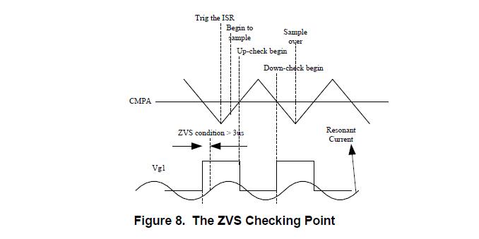
To check the PWM ZVS condition, the counter value and the counter direction of the ePWMx
module are recorded. The Up-check start point and the Down-check start point can also be
calculated; these points are the turning on point and turning off point, respectively, of the PWM
when the dead-time is ignored.
The PWM ZVS condition is checked in every two switching cycles. When the two cookers are
turned on together, the two checks are done in the EPWM ISR, which has a lower PWM
frequency.
4.3.2 ZVS Checking
When the 1-MHz ADC sampling completes, it is important to determine from which point the
check operation starts. As previously mentioned, the 1-MHz ADC sampling not only records the
current sensing value, but also records the counter value and the count direction at the same
time. So from the counter value and direction, the start point can be determined. However, the
CPU must check the counter value and the direction one by one, which will cost a lot of the CPU
time. To save the CPU time, the calculation of the start point is needed.
Assume the CMPR is the compare value of the EPWM value, PRD is the period count of the
PWM cycle. Cnt_Start_Sample is the counter value of the first ADC sampling. 1us_Cnt is the
counter value per sample.
The up-check start point is:
UpCheckPoint = (CMPR – Cnt_Start_Sample)/1us_Cnt;
The down-check start point is:
DownCheckPoint = (CMPR – Cnt_Start_Sample + PRD/2)/1us_Cnt;
Why ?
