Hi,
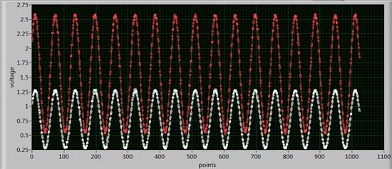
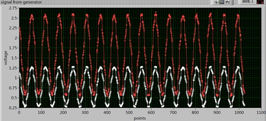
I am using TMS320F2812 ADC in the simultaneously sampling, Continuous run, and cascaded sequence model,only sampling channel a0 and channel b0. But i find the sampling rate is not stable, and lower than the rate I calculate according to the datasheet. The picture of the signal sampled by the dsp chip and my code are listed below. I do not know why the sampling interval is not identical.
My target sample rate is the highest speed of th ADC in TMS320F2812. About 8.33MSPS, I am not sure, and i am testing it. The speed of the input sinusoid if 35KHZ. 1MSPS is enough for 35khz sinusoid, but I just would like to test the speed of f2812 adc. I would like it can work at the highest speed, namely, 12.5msps for one channel continuously sampling and 8.33msps for two channels simultaneously and continuously sampling.
I have been using optimization level 2 (2 Global Optimization in ccs6.0 )all the time.Maybe it is not the optimization problem.
Thank you.
//this programm is used to verify sampling AINA0 and AINB0 simutaneously.
#include "DSP281x_Device.h" // DSP281x Headerfile Include File
#include "DSP281x_Examples.h" // DSP281x Examples Include File
#include <STDIO.H>
// ADC start parameters
#define ADC_MODCLK 0x3 // HSPCLK = SYSCLKOUT/2*ADC_MODCLK2 = 150/(2*3) = 25MHz
#define ADC_CKPS 0 // ADC module clock = HSPCLK/1 = 25MHz/(1) = 25MHz
#define ADC_SHCLK 5 // S/H width in ADC module periods = 16 ADC cycle
#define AVG 1000 // Average sample limit
#define ZOFFSET 0x00 // Average Zero offset
#define BUF_SIZE 2048 // Sample buffer size
// Global variable for this example
Uint16 SampleTable[BUF_SIZE];
main()
{
unsigned long int i;
int shclk;
Uint16 array_index;
char*msg, char_result[20];
//Initialize System Control:
// PLL, WatchDog, enable Peripheral Clocks
// This example function is found in the DSP281x_SysCtrl.c file.
InitSysCtrl();
// Specific clock setting for this example:
EALLOW;
SysCtrlRegs.HISPCP.all = ADC_MODCLK; // HSPCLK = SYSCLKOUT/ADC_MODCLK
EDIS;
// Initialize GPIO:
// This example function is found in the DSP281x_Gpio.c file and
// illustrates how to set the GPIO to it's default state.
// InitGpio(); // Skipped for this example
// Enable the pins as XF pin as output
EALLOW;
GpioMuxRegs.GPFMUX.bit.XF_GPIOF14 = 1; //enable XF pin on GPOF14
EDIS;
// Clear all interrupts and initialize PIE vector table:
// Disable CPU interrupts
DINT;
// Initialize the PIE control registers to their default state.
// The default state is all PIE interrupts disabled and flags
// are cleared.
// This function is found in the DSP281x_PieCtrl.c file.
InitPieCtrl();
// Disable CPU interrupts and clear all CPU interrupt flags:
IER = 0x0000;
IFR = 0x0000;
//SCI B setting.
scib_fifo_init(); // Initialize the SCI FIFO
scib_init(115200); // Initalize SCI for echoback
msg = "\r\nThis is ADC testing.\r\n";
scib_msg(msg);
/*
do{
// Wait for inc character
while(ScibRegs.SCIFFRX.bit.RXFIFST!=1) { } // wait for XRDY =1 for empty state
// Get character
ReceivedChar = ScibRegs.SCIRXBUF.all;
}while(ReceivedChar!='\r'&& ReceivedChar!='\n');
*/
//SCI B setting end.
// Initialize the PIE vector table with pointers to the shell Interrupt
InitPieVectTable();
// Specific ADC setup for this example:
InitAdc(); // power up ADC
AdcRegs.ADCTRL1.bit.ACQ_PS = ADC_SHCLK; // Simultaneous mode enabled: Sample rate = 1/[(3+ACQ_PS)*ADC clock in ns]
// = 1/(18*40ns) =1.388888888MHz
// If Sequential mode: Sample rate = 1/[(2+ACQ_PS)*ADC clock in ns]
AdcRegs.ADCTRL3.bit.ADCCLKPS = ADC_CKPS;
AdcRegs.ADCTRL1.bit.CONT_RUN = 1; // Setup continuous run
//Simultaneous Sampling Cascaded Sequencer Mode Example
AdcRegs.ADCTRL3.bit.SMODE_SEL = 1; // Setup simultaneous sampling mode
AdcRegs.ADCTRL1.bit.SEQ_CASC = 1; // Setup cascaded sequencer mode
AdcRegs.ADCMAXCONV.all = 0x0007; // 2 double conv s (16 total)
AdcRegs.ADCCHSELSEQ1.all = 0x0; // Setup conv from ADCINA0 & ADCINB0
AdcRegs.ADCCHSELSEQ2.all = 0x0; // Setup conv from ADCINA0 & ADCINB0
AdcRegs.ADCCHSELSEQ3.all = 0x0; // Setup conv from ADCINA0 & ADCINB0
AdcRegs.ADCCHSELSEQ4.all = 0x0; // Setup conv from ADCINA0 & ADCINB0
// User specific code, enable interrupts:
// Clear SampleTable
for (i=0; i<BUF_SIZE; results="results" read="read" int1="int1" for="for" wait="wait" while="while" shclk="0;" array_index="0;" adcregs="1;" seq1="seq1" sampletable="((AdcRegs.ADCRESULT0)" i="0;" start="start">>4);
SampleTable[array_index++]= ((AdcRegs.ADCRESULT1) >>4);
SampleTable[array_index++]= ((AdcRegs.ADCRESULT2) >>4);
SampleTable[array_index++]= ((AdcRegs.ADCRESULT3) >>4);
SampleTable[array_index++]= ((AdcRegs.ADCRESULT4) >>4);
SampleTable[array_index++]= ((AdcRegs.ADCRESULT5) >>4);
SampleTable[array_index++]= ((AdcRegs.ADCRESULT6) >>4);
SampleTable[array_index++]= ((AdcRegs.ADCRESULT7) >>4);
// Wait for INT1
while (AdcRegs.ADCST.bit.INT_SEQ1== 0){}
AdcRegs.ADCST.bit.INT_SEQ1_CLR = 1;
//Read results
SampleTable[array_index++]= ((AdcRegs.ADCRESULT8) >>4);
SampleTable[array_index++]= ((AdcRegs.ADCRESULT9) >>4);
SampleTable[array_index++]= ((AdcRegs.ADCRESULT10) >>4);
SampleTable[array_index++]= ((AdcRegs.ADCRESULT11) >>4);
SampleTable[array_index++]= ((AdcRegs.ADCRESULT12) >>4);
SampleTable[array_index++]= ((AdcRegs.ADCRESULT13) >>4);
SampleTable[array_index++]= ((AdcRegs.ADCRESULT14) >>4);
SampleTable[array_index++]= ((AdcRegs.ADCRESULT15) >>4);
if(array_index>=BUF_SIZE)break;
}
for(array_index=0;array_index<BUF_SIZE;array_index++){
sprintf(char_result,"%9.6f#\0",SampleTable[array_index]*3.0/4096.0);
scib_msg(char_result);
//scib_xmit(SampleTable[array_index]/256);
//scib_xmit(SampleTable[array_index]%256);
//scib_msg("\r\n");
msdelay(2);
}
scib_msg("\r\n\r\nADC testing is over.\r\n");
}
//===========================================================================
// No more.
//===========================================================================


