This thread has been locked.

If you have a related question, please click the "Ask a related question" button in the top right corner. The newly created question will be automatically linked to this question.

HRPWM Example issues on 28075

Other Parts Discussed in Thread: CONTROLSUITE

I started with the 2 HRPWM examples (hrpwm_duty_sfo and hrpwm_prdupdown_sfo) and I don't see what I expect.

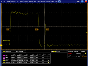
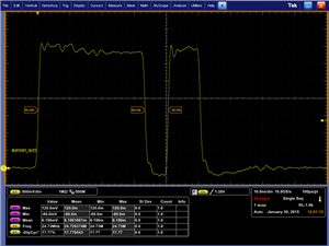
On the duty example, the MEP appears to function, but there is a range at the lower end of the duty-cycle that is produced that appears to have a cycle low and high in the middle of the pulse (obviously turning it into two shorter pulses).  Strange.

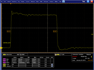
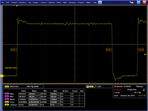
For the prdupdown example there is a problem with the MEP behavior.  It never moves the edge finer than the 60 MHz EPWM clock rate.  One behavior that I don't understand is that the example holds the TBPRD fixed (meaning the EPWM edge should not be changing) and only the TBPRDHR register is modified, meaning I would expect only MEP sized changes in the period.  What I observe is that the edge moves by 16.8 ns (one tick of a 60 MHz clock, which is what the EPWM should be running at if I read the example code correctly) over the entire sweep of TBPRDHR settings that are written by the example.

Are you able to reproduce any of this on your end?  I assume these examples apply to other devices as well and perhaps have not actually been tried on this new chip.

  • Additional detail on the "glitch" in the duty-cycle example. Values for DutyFine up to 0x2AAA exhibit the extra pulse. Values 0x2AAB and higher do not glitch.

    The glitch's falling edge is 33.16 ns after the expected rising edge. This is 2 ticks of the EPWM's 60 MHz. The rising edge of the glitch is about 7 ns after the falling edge of the glitch.

  • Joe,

    It sounds like there may be a bug in the example for this device.  I'll investigate both of these and get back in touch soon.

    Can you verify the hardware you are running this on?  Have you modified the example at all?  Is your SYSCLK also 60 MHz?

    Thanks,

    Kris

  • Hi Kris,

    I'm running on the F2807x controlCARD R1.1 with a F28075 on it.

    The example was not modified with the exception of changing the sysclk to use the external xtal since the hardware I'm running on has an uncalibrated internal clock (and I need a stable, accurate clock). The sysclk should be running at 120 MHz and the EPWM at 60 MHz (due to the EPWMCLKDIV = 2).
  • Any further ideas on this? I haven't been able to resolve it so far.
  • Hi Joe,

    I believe this might be a header file issue with the HRPWM.  I should be able to confirm this early next week.

    Kris

  • Do you have any further details on the header file issue?

    Thanks,

    -Joe

  • Joe,

    It turns out the suspected header file issue seems to be OK in the examples.  Can you confirm you are using the v140 projects?

    For the hrpwm_duty_sfo example- can you give me your CMPA/CMPB register 32 bit values when DutyFine = 0x2300, 0x2AAA, 0x2AAB, and 0x7000?  Also please include the value of the HRMSTEP register.  Can you try enabling the AUTOCONVERT define and see if the extra pulse issue goes away for you?

    Thanks,

    Kris

  • Hi Kris,

    I'm using v130 examples since that's what was available when I installed 4 weeks or so ago. I just installed the v140 stuff last night and there doesn't seem to be a difference in behavior at least for the hrpwm_duty_sfo example (didn't try others yet).

    AUTOCONVERT had no effect on the behavior.

    I'll post the register values you asked for in a bit. Is it good enough to post what is written or should I read back from the registers?

    Thanks,
    -Joe

  • Joe,

    Actually, that question reminded me of something.  Can you confirm you're using Rev0 silicon?  Which PWM are you testing?  Take a look at the errata for the HRCNFG register:

    www.ti.com/.../sprz412c.pdf

    For CMPA / CMPB the emulator reads from the Expressions window should be fine.

    Thanks,

    Kris

  • I'm monitoring the HRPWM1, but I believe the example configures all of them.
  • HRMSTEP = 0x0070

    DutyFine: 0x2300   CMPA: 0x00023400

    DutyFine: 0x2AAA  CMPA: 0x00027000

    DutyFine: 0x2AAB  CMPA: 0x00030000

    DutyFine: 0x6FFF   CMPA: 0x00076200

  • This glitch must be a manifestation of the requirement described in the data sheet.

    13.2.4.3 Duty Cycle Range Limitation

    "...the duty cycle must not fall within the restricted range. Otherwise, there may be undefined behavior on the ePWMxA output."

    I guess the example should be modified to ensure that CMPx is never less than 0x30000.

    That still leaves an unanswered question about the period adjustment. I retested the v140 hrpwm_prdupdown_sfo example and there is no MEP behavior at all. It simply steps the EPWM steps. Ideas?
  • Joe,

    I did confirm that the hrpwm_prdupdown_sfo example is not display the MEP movement as you are seeing.  I also saw different behavior on EPWM1 than the other EPWMs.  I'm out of the office this week so I'm going to see if one of my colleagues can pursue the debug further so we can get you an answer sooner.

    Thanks,

    Kris

  • Joe,

    We have found the issue.  Comment out the following line in the HRPWM_Config() function:

    //    (*ePWM[j]).TBCTL.bit.PHSEN = TB_ENABLE;             // TBCTR phase load on SYNC (required for updown count HR control

    What is happening is the example is only setup for MEP movement on EPWM1.  However, this line of code on the F28x7x devices enables EXTSYNCIN1 as a sync source for EPWM1.  By default, EXTSYNCIN1 is a value of '0' which defaults to GPIO0.  Since EPWM1 is outputting on GPIO0 it is in effect syncing itself preventing the entire PWM cycle from completing (and hence the MEP movement).

    I will have this example corrected for the next controlSUITE release.  

    Thanks,

    Kris

  • Disabling that seems to disagree with the datasheet, but it did fix the example. Even the comment at the end of the line states that it is "required for updown count HR control".