This thread has been locked.

If you have a related question, please click the "Ask a related question" button in the top right corner. The newly created question will be automatically linked to this question.

SPLL_1ph_ IQ doesn't work (PWM at 20kHz - Grid freq at 50 Hz)

Other Parts Discussed in Thread: CONTROLSUITE

Hello,

I tried to use SPLL_1ph_iq library but it doesn't work. I place a generator to simulate 50Hz, on

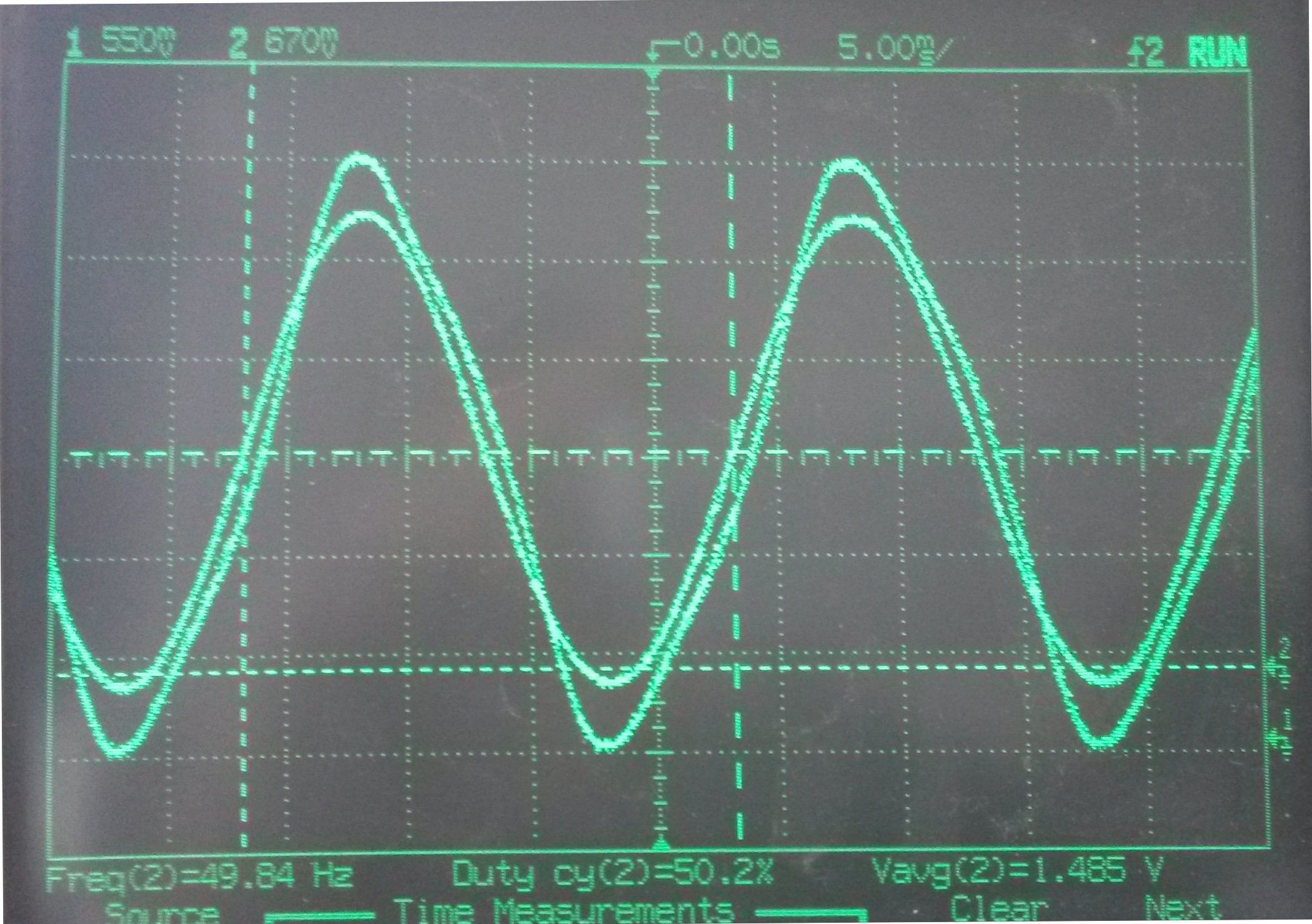
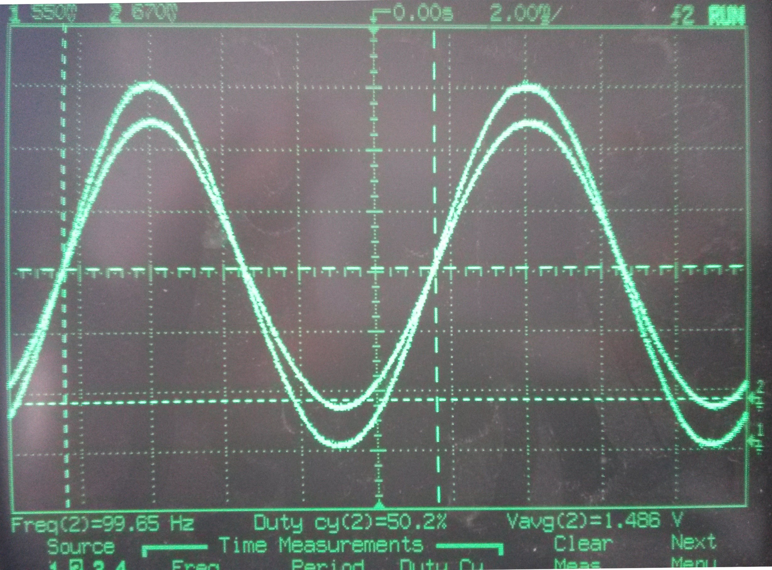
PWMDAC I saw sinwave correctly but othing about SPLL.

PWM interrupt is at 20 kHz I check with pwm it is well at 20 kHz

Parameters implemented are :

    // loop filter coefficients for 20kHz at 50 hz grid network
    spll_obj->lpf_coeff.B0_lf=SPLL_Q(166.9743);
    spll_obj->lpf_coeff.B1_lf=SPLL_Q(-166.266);
    spll_obj->lpf_coeff.A1_lf=SPLL_Q(-1.0);

Within main interrupt following code is executed :

    //NOTCH PLL
    spll1.AC_input = (long)(_IQmpy(Generator1.sinus,_IQ(0.8))>>3); // Q24 to Q21
    SPLL_1ph_IQ_FUNC(&spll1);
    //SPLL_1ph_IQ_MACRO(spll1);

    //==========================================================
    //  Connect inputs of the PWMDAC module
    //==========================================================
    PwmDacCh1 = (int16) _IQ21toIQ(_IQtoIQ15(spll1.AC_input)); //>_IQtoIQ15(Generator1.sinus);
    PwmDacCh2 = (int16)_IQtoIQ15(Generator1.sinus); //(spll1.theta[0]>>6);
    PwmDacCh3 = (int16)_IQ21toIQ(_IQtoIQ15(spll1.Upd));
    pwmdac1.update(&pwmdac1);

What do you suggest to test it ?

Please let me know.


regards,

Ol

  • I changed library version from V1.2 to V1.1 with SPLL_1ph.h and now I have got a signal, distorted but a signal !

    I programmed with F28035.

    Signal is distorted on PWMDAC and when i increase GRID frequency (from 50 Hz up to 120 Hz) with internal function generator the signal goes better. More I increase frequency and more signals are synchronized and sinus.

    I will try to check parameters of low pass and notch filter thanks to excel file given in V1.2.

    Any idea will be welcome 

    Thanks in advance

  • My first suggestion will be to use the

    C:\ti\controlSUITE\development_kits\SolarExplorer\SolarExplorer_PVInverter_F2803x\~Docs

    software to run the experiment, 

    Make sure you are calling both the init functions, we provide an adaptive notch function which you can call with the grid frequency value.

    SPLL_1ph_IQ_init(GRID_FREQ,_IQ21((float)(1.0/ISR_FREQUENCY)),&spll1);

    SPLL_1ph_IQ_notch_coeff_update(((float)(1.0/ISR_FREQUENCY)),(float)(2*PI*GRID_FREQ*2),(float)0.00001,(float)0.1,&spll1);

    Also make sure GridMeas has zero DC offset, i.e. it goes from -1 to 1, if there is offset on the signal you need to sutract to make it fall in this range

    spll1.AC_input =(long)(GridMeas>>3);