This thread has been locked.

If you have a related question, please click the "Ask a related question" button in the top right corner. The newly created question will be automatically linked to this question.

Trouble writing memory block

Other Parts Discussed in Thread: TMS320F28335

Hi

I am facing issues with CCSv6.0, TMS320F28335 while working with a power electronic circuit. I am using ADC,ePWM,CAN in broader terms.

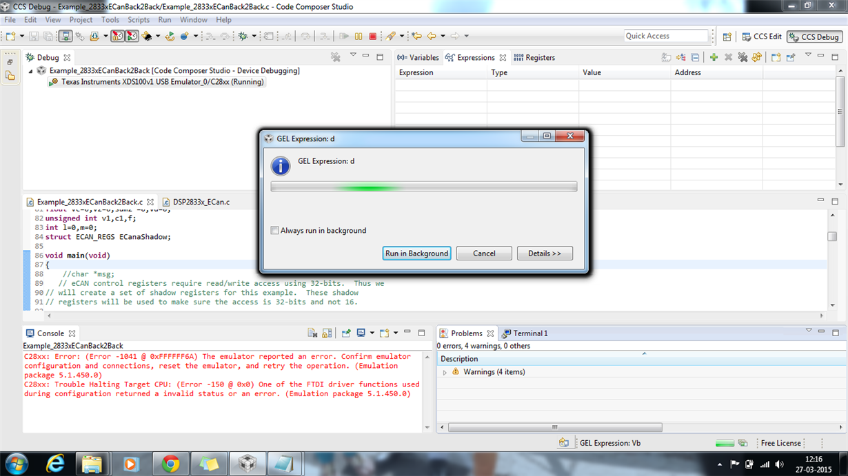
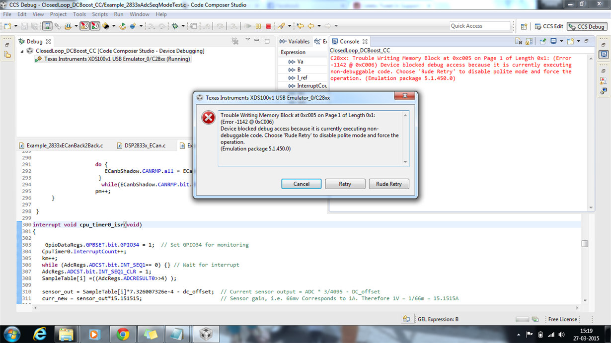
The program works fine with the power electronic converter while sensing ADC and generating PWM, But when CAN communication code is included it faces some issues. The screenshots are attached below:

When I disable the real time mode, program seems to be working fine. But if real time mode is enabled as is desired, it either hangs, does not load or gets debugged and then throws away the error and performs nothing.

Kindly suggest some solutions.

Thanks & regards

Sneha

  • Hi Sneha,

    So you're working with DC/DC converters? Also, does this happen at high power?

    Regards,
    Gautam
  • Hi gauatm

    Yes I am working with DC-DC converters.

    And this happens at low power, I have not even crossed 5W. Don't know how system will react when I operate it at high power.

    Do the sequence of initialization affect this? And if yes, where and How can I find the correct sequence.

    Thanks & Regards

    Sneha

  • Do the sequence of initialization affect this? And if yes, where and How can I find the correct sequence.

    Just check the interrupt acknowledgements. Sequence will not matter.
    Go through the interrupt vector table and find out the priorities of the peripherals you're using. Once, you get that info... just check you're code flow and check for any collisions.

    You can try using Interrupt Nesting: processors.wiki.ti.com/.../Interrupt_Nesting_on_C28x

    Regards,
    Gautam
  • Ya sure, I will check the program flow and the interrupt acknowledgements.

    Actually the CAN program and the converter program works fine individually.The problem arises only when the two are merged together.
    Thanks & Regards
    Sneha
  • Check for the interrupts that are in same group... with eCAN
  • To me it sounds like an electrical problem (ground connection?). When exactly does the error pop-up? When do you electrical connect the two board over CAN? Are they permanently connected?
  • HI Frank

    The error pops-up mostly when real time mode is enabled. I am not very sure with the working when real time mode is disabled.

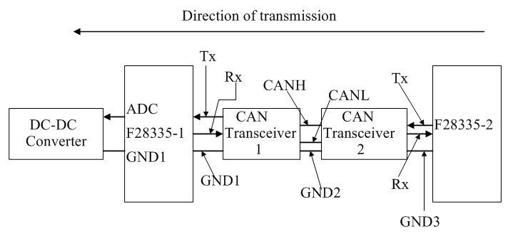
    The two boards are connected through F28335 in between:

    Something similar to below diagram:

    For now I am not even sure whether F28335-1 is recieving any data from F28335-2 or not, as the error pops up and halts the program.

    Thanks & Regards

    Sneha

  • Hi All

    The program seems to be working fine, when real time mode is disabled.

    I am using ADCseqmodetest program for ADC sensing with ePWMtimer modified as per my requirement. The problem which I am facing now is that the duty cycle is being updated every 10 us and data transmission through CAN takes a min of 140 us. So when the program is run together it halts at ADC int and doesnt even sense ADC.
    I have kept the can loop independent of the controller loop and as per my understanding,the program should run and CAN value would update only after 140 us and ADC value keeps updating and hence duty cycle after 10 us. But it halts at
    while (AdcRegs.ADCST.bit.INT_SEQ1== 0) {} // Wait for interrupt

    I can not understand the relation between CAN timing and programming halting at this point.
    Any help would be appreciated.

    Regards
    Sneha
  • HI All

    The problem is resolved.

    It was the issue related to ADCINT .

    Thanks for the support.

    Regards

    Sneha