This thread has been locked.

If you have a related question, please click the "Ask a related question" button in the top right corner. The newly created question will be automatically linked to this question.

Error is occured using external X-tal in customized board

Other Parts Discussed in Thread: TMS320F28377D, CONTROLSUITE

Hello,

I make a test board using 28377D.

But, there is a error when using external X-tal.

I used CX5032GB20000(20Mhz) as X-tal and designed the board referring to the spruhm8a (tms320f28377D Manual).

As the clock source is crystal, I selected the option 'b)' in page 108 of the manual.

I also did not connect Vssosc pin to the board ground, because when using external crystal the pin has to be disconnected to the board ground as written in the sprs880a (tms320f28377d datasheet).

However, the error is occured during connecting the board.

The error code is this.

Error connecting to the target:
(Error -233 @ 0x0)
The JTAG IR and DR scan-paths cannot circulate bits, they may be broken.
An attempt to scan the JTAG scan-path has failed.
The target's JTAG scan-path appears to be broken
with a stuck-at-ones or stuck-at-zero fault.
(Emulation package 5.1.641.0)

But interesting thing is this. When the Vssocs pin is connected to the board ground(what the datasheet do not recommend), the board works well.

My question is,

1) what is problem about the error? is there any non-provided connecting method which I did not know?

2) Is it okay using the Vsscos pin to connect with the board ground what the datasheet says "do not connect"

Thanks,

Sungho

  • Hi Sungho,

    Did you follow the controlCard schematics: C:\ti\controlSUITE\development_kits\~controlCARDs\TMDSCNCD28377D_v1_3\R1_1_A
    Check the configuration there, following that would clear your doubts.

    Regards,
    Gautam

  • Hi Sungho,

    Are you still experiencing trouble with this?  If so, will you upload your xtal circuit schematic along with the xtal oscillator model #?

    2. This config can work however, it is possible that the board ground noise is being injected onto the oscillator.  It is recommended to not connect VSSOSC to board ground as VSSOSC is a kelvin ground for the xtal oscillator.

    Please let me know if the issue is closed so I can close this ticket.

    Best Regards,
    Adam Dunhoft

  • Hi Gautam,

    Thank you for your help. So, I saw the schematic which you said and also saw the schematic of 28377S launchpad(LAUNCHXL-F28377S).

    I take a screenshot of clock part of each schematic, and I found some differences.

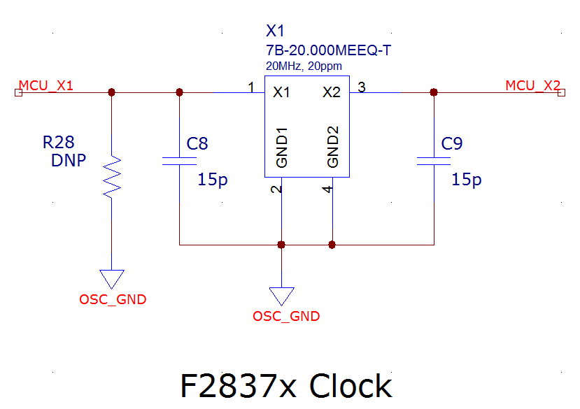
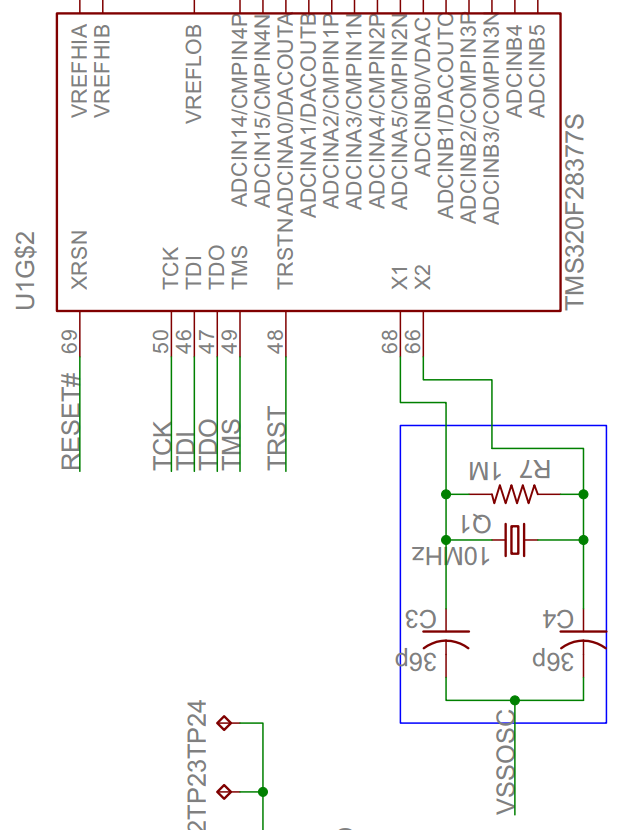
    <TMDSCNCD28377D>                                            <LAUNCHXL-F28377S>

     \

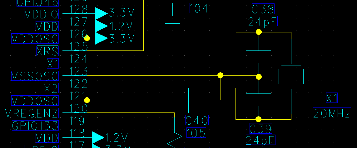
    <Our test board>

    The difference between two schematic and our test board is just existence of resistor.

    So, I connect resistor between X1 and OSC_GND as shown in TMDSCNCD28377D, and

    connect resistor between X1 and X2 as shown in LAUNCHXL-F28377S.

    However, both of tries didn`t draw good results.

    Best regards,

    Sungho.

  • Hi Adam,

    Thank you for your concern. I used a 20Mhz crystal of CX5032GB(Kyocera).

    Unfortunately, the datasheet of crystal didn`t contain example circuit.

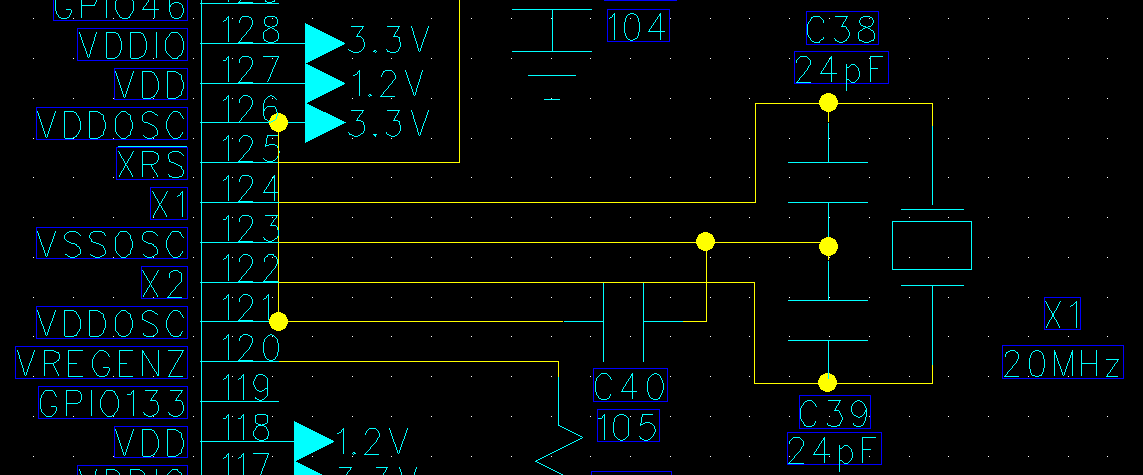
    I attached my circuit schematic and the datasheet of crystal.

    I hope a small clue can be found.

    Best regards,

    Sungho.

    CX5032GB.pdf

  • Hi Sungho,

    A few things here:

    1.) The XTAL you have chosen has an ESR spec of 100 ohms which is out of spec for F28377x (ESR spec is 50 ohms MAX @ 20MHz with CL1=CL2=24pF). See Table 5-15 in DS.

    2.) VSSOSC should only connect to CL1 and CL2 capacitors. C40 should be removed from VSSOSC. The decap for VDDOSC should connect to board ground. See Figure 5-6 in DS.

    3.) The resistor between X1 and X2 is unnecessary. See Figure 5-6 in DS.

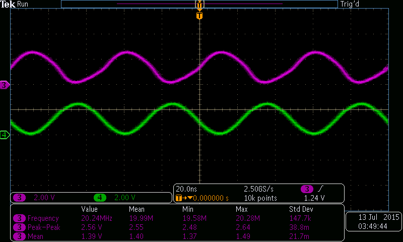
    Please scope the X1 pin. Does the XTAL oscillate? Post the waveform here.

    Best Regards,
    Adam Dunhoft
  • Hi Adam,

    Thank you for your help again.

    I got to know what is the problem from what you said.

    I will use other XTAL satisfying ESR spec and post the result when the ordered XTAL comes.

    Here is my X1, X2 waveform.

    The purple one is waveform of X1 pin and the green one is that of X2 pin.

    I think oscillation input X1 is fine, and also oscillation output X2 is fine.

    I will post result with the updated experiment.

    Sincerely,

    Sungho Son.

  • Hello Sungho Son,

    Is this still open or do you have a solution which you can post?

    Best Regards,

    Adam Dunhoft