This thread has been locked.

If you have a related question, please click the "Ask a related question" button in the top right corner. The newly created question will be automatically linked to this question.

Solar inverter DC-AC Kit

Other Parts Discussed in Thread: CONTROLSUITE

Hi,

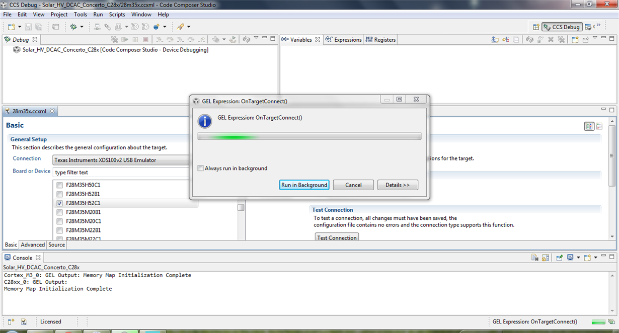
I am using solar inverter DC-AC kit, my control card is F28M35. When I ran the off grid test, LED 2 wasn't lighted. I used external +15V adapter and the LED 1 was lighted. When I tuned DC source to 300V, LED 2 wasn't lighted. I checked the program, HV_SOLAR_DC_AC_v1.1\Solar_HV_DCAC_Concerto_SCI_Rev_0. When I debug it, it shows this GEL Expression: OnTargetConnect().

Please help me.

  • Please review the Quick Start Guide for the kit. Step 4 says, for external +15V supply you have to power the external supply and then turn on S1. At this point LED2 should be flashing in every 1 sec. If it does not, then check the external power supply.

    You can also power up the board with the on-board aux supply. In that case you have to turn on S1 first. Then power the high voltage DC source and regulate the bus at 300V. At this point LED 2 should be flashing.

    Also check the jumper setting in Table 1.2

    Shamim

  • Thank you for your reply! I did as the QSG said, open jumper JP1, JP3 for external power. I also tried on board power supply, but it didn't make any difference. I followed the steps on 2.3 section, but it doesn't work.
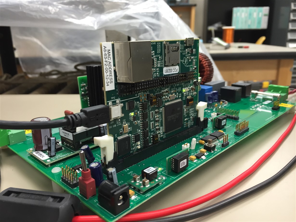
  • I used on board power this time. Here is the figure.

  • Do you get 3.3V supply to the control card? Pls check this. If not you will have to get the kit replaced.

    Shamim

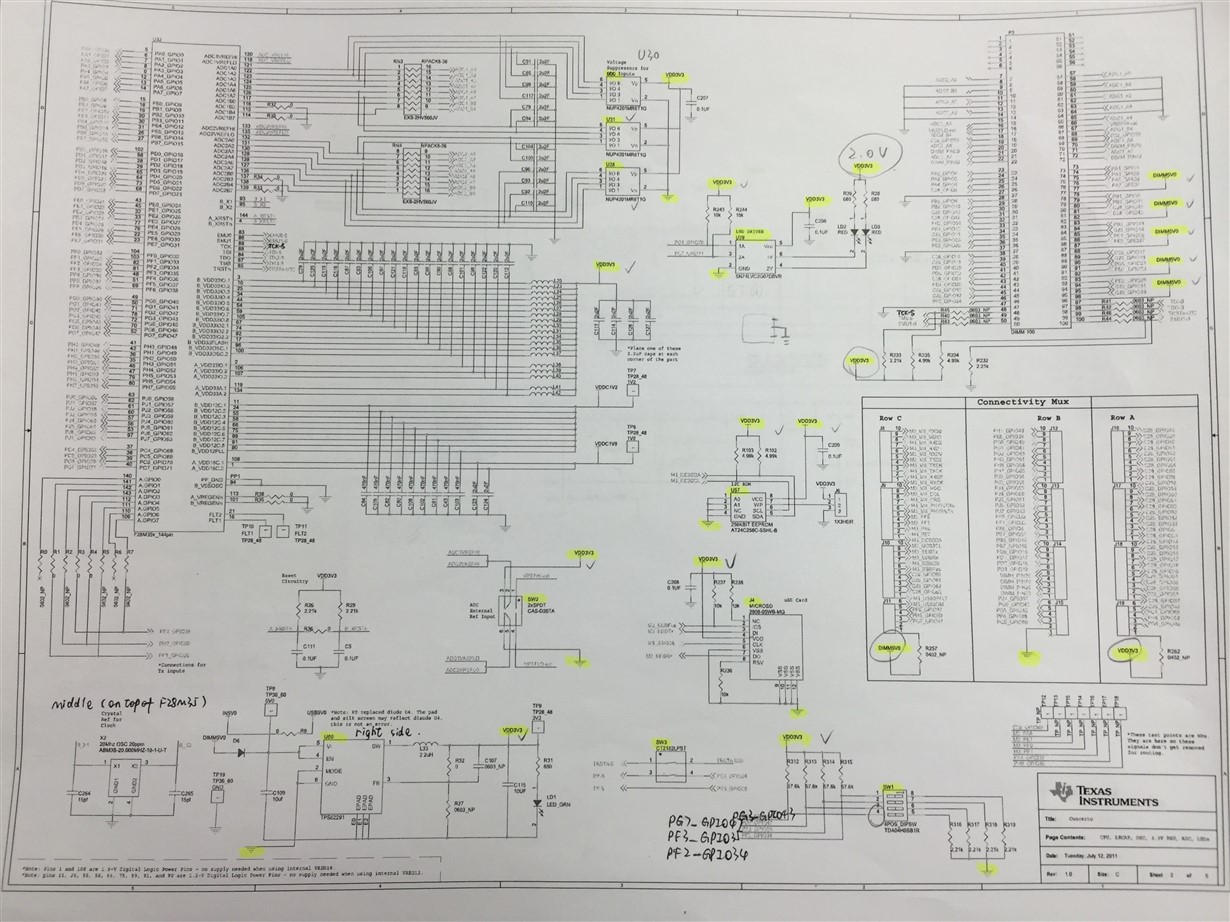
  • Hi, I tested the voltage on DIMM-100, DIMM5V0 pins were ok, Pin 48, Pin 50 and Pin 100 on DIMM-100 were 0V, which should be 3.3V. I also checked the control card Connectivity Mux, PIN A1 should be 3.3V, but I got 0V. PIN C1 should be 5V, I got nearly -3.2V. The SW1 pin4 should be 3.3V, but I got 0V. Pin 4 and Pin 6 on Led driver U29 were supposed to be 3.3V, I got 2.0V. Should I need to replace the development kit?

  • Jiao, I face the same problem like yours. And still do not know what to do next. I even do not know anything else since I have expected that I should be able to test the HV Solar INVERTER kit without having to connect to a computer or a laptop. I assume that the INVERTER should be tested as a stand-alone hardware without being interfaced to a computer since the QSG implies that is possible. I have not prepared to learn to use any other supporting tool such as GUI, Composer ControlSuite, or Composer Studio. I am just a typical analog engineer who is very naïve in Micro-controller area.
  • Shamim,

    According to QSG, "Short the No.18 pins of the Port A and Port B, besides, short the No.4 pins of the Port A
    and Port B",

    Is this instruction also applicable to the stand-alone DC-to-AC inverter kit without using the front-end DC-DC EVM ?

    If YES, where can I get a jumper for No. 18 pins ?

    Since on pins 18, there is no jumper provided in the first place (as being shipped to me that way).

    My MCU control board is F28M35xx Release 1.0.

    Kasemsan
  • I really feel disappointed. The LD2 on control card still doesn't flash. I don't know the reason and what to do. Does your LD2 flash?
  • Jiao, I still have the same problem like yours.
  • Yes, this is applicable for the Inverter running without the other DC-DC EVM.

    If the jumper is not there then you have to somehow short those with wires or find a jumper similar to that shown on the picture.

    Shamim

  • It seems like your board has some problems and you need to get a replacement.

    Shamim
  • Hi, Shamim, I think it might be broken in C28 flash. Now I can download program into M3 core, but I cannot download the program into C28. I tried twice, never succeed. I just saw someone had the same problem like me and he claimed that the C28 flash might be broken. Here is the error information:

    Cortex_M3_0: GEL Output: Memory Map Initialization Complete
    Cortex_M3_0: GEL Output: Watchdog Timers Enabled
    Cortex_M3_0: GEL Output: UARTs Enabled
    C28xx_0: GEL Output:
    Memory Map Initialization Complete
    C28xx_0: GEL Output:
    RAM Initialization Complete
    C28xx_0: Loader: One or more sections of your program falls into a memory region that is not writable. These regions will not actually be written to the target. Check your linker configuration and/or memory map.
    C28xx_0: File Loader: Verification failed: Values at address 0x000000000013E000 do not match Please verify target memory and memory map.
    C28xx_0: GEL: File: D:\ti\controlSUITE\development_kits\HV_SOLAR_DC_AC_v1.1\Solar_HV_DCAC_Concerto_SCI_Rev_0\c28\ccs\Debug\Solar_HV_DCAC_Concerto_C28.out: a data verification error occurred, file load failed.

    If I replace the control card, which address do I need to mail to? Thank you for your help!

  • Shamim,

    I followed your advice but the problem remains the same. LD2 not flashing even I ramp up the HV input voltage above 300 V (like 380V).

    All voltages +5V, and 1.65 V to the MCU control card are available and normal.

    I also explore USB connection with GUI software with the kit. The USB communication is also got stuck as well.
  • You are using the Quick Start guide to run the board. Since this mode does not work there must be something wrong with the board. So I suggest you use the User Guide (this is another doc, not the quick start guide) and go through the code step by step, starting from build 1 (as explained in the user guide) and get familiar with the code. Then try to debug the hardware problem and see what's wrong with the board.

    Shamim
  • Hi, Shamim,

    I ordered another new development kit and I still have this problem. I used on board power supply, opened jumper 3 and jumper 6. The control card is F28M35, shorten No.4 and No.18 pin. I connected 31 ohm resistor as load. Turn on S1 first, then power on. When I applied to 300V DC(even a litter higher than 300V), LED2 is still not flashing. I didn't change the program in the control card yet. Hope you could help me! Thank you!

    Jiao Jiao
  • I had a same problem like yours. I can have LD2 lighten up just in grid-tie mode. I debug both M3 and C28 program into the MCU and I get LD3 flash in every second, but LD2 is off. I successfully connect the MCU with the GUI operation interface, and click grid-tie enable, the LD3 will be flashing each second. However, after I regulate both DC(380V) and AC(115V) and click the turn on button on the interface, the first time I click it, the LD3 will turn off, and the system did not turn on, when the second time I click the turn on button, the LD3 is always on but LD2 is still off. When I see the oscilloscope, I get output current of the inverter is 2.67 A RMS and 2.2A load current for the AC source, which is close to the value in the document. And I try to modify the dwVoltageLoopOutConst in the program named Solar_HV_DCAC_Concerto_C28.c, I wanna reduce the output current and change the line 1062 dwVoltageLoopOutConst = _IQ24(0.18); to dwVoltageLoopOutConst = _IQ24(0.09); , after I reload the program, the experimental phenomenon is the same.

    Could you please help me to define the problems, why the LD3 lighten on and the turn on failed. I followed the document and I do not think there was any mistake in my connection, and I did not change anything in the program. By the way, was the correct operation I had in order to change the out current constant?
  • I already sent you a friend request, please check it. I guess our project are pretty much the same. If you do not mind, we can talk personally.
  • I added you in Wechat.
  • Hi Shamim,

    I had a same problem like hers. I can have LD2 lighten up just in grid-tie mode. I debug both M3 and C28 program into the MCU and I get LD3 flash in every second, but LD2 is off. I successfully connect the MCU with the GUI operation interface, and click grid-tie enable, the LD3 will be flashing each second. However, after I regulate both DC(380V) and AC(115V) and click the turn on button on the interface, the first time I click it, the LD3 will turn off, and the system did not turn on, when the second time I click the turn on button, the LD3 is always on but LD2 is still off. When I see the oscilloscope, I get output current of the inverter is 2.67 A RMS and 2.2A load current for the AC source, which is close to the value in the document. And I try to modify the dwVoltageLoopOutConst in the program named Solar_HV_DCAC_Concerto_C28.c, I wanna reduce the output current and change the line 1062 dwVoltageLoopOutConst = _IQ24(0.18); to dwVoltageLoopOutConst = _IQ24(0.09); , after I reload the program, the experimental phenomenon is the same.

    Could you please help me to define the problems, why the LD3 lighten on and the turn on failed. I followed the document and I do not think there was any mistake in my connection, and I did not change anything in the program. By the way, was the correct operation I had in order to change the out current constant?

    Luo Liu
  • Hi Shamim,

    I also have the same problem with one of my F28M35 control cards.

    Actually I have two F28M35 control cards, but I can see they are in different version(both the chip and the PCB board). The old one worked well but the new one didn't work(the red light didn't flash). I guess it's some hardware problem.

    The number on the chip that didn't work is "F28M35H52C1RFPT YFB-39C78RW G4"

    The one work well is "F28M35H52C1RFPT YFB-41AJZ9W G4"


    Thanks,

    Dong

  • Thanks for your input.

    Did you try both control cards after loading the .out file (that comes with the F28M35 CCS project) into the flash? Just making sure that the control card was programmed before power up.

    Shamim