This thread has been locked.

If you have a related question, please click the "Ask a related question" button in the top right corner. The newly created question will be automatically linked to this question.

A/D conversion of LVDT signal conditioner output

Other Parts Discussed in Thread: TMS320F28335, CONTROLSUITE

Hi, 

       Please advise as how can I perform the A/D conversion of the analog output from LVDT signal conditioner which gives an output between 1.5 to 2.5 volts for a linear actuator which moves between the range of  (2 and -2) mm. I hope the voltage levels at the output of signal conditioner are in the acceptable range of the input of the DSP A/D port.  I need advise on the following

1) Any tips for the connections between signal conditioner analog DC output and A/D port of the TMS F28335.

2)  Which blocks to use in simulink to perform the A/D conversion and visualize the LVDT data in simulink.

Thanks.  

  • Aero,


    I'm moving this post to the C2000 32-bit Microcontrollers Forum (the Precision Data Converters Forum usually handles the stand-alone 16- and 24-bit data converter questions).

    Since this questions deals with the TMS320F28335 microcontroller's data converter, I think you'll find and answer here.


    Joseph Wu
  • Aero,

    I'm assuming your signal conditioner delivers a buffered DC signal for fixed armature position (i.e. all the signal conditioning is done before the F28335).  If so, the signal is within the 0-3V input range of the F28335 ADC.  You may choose to apply an offset (-0.5V) and gain (3x) to make optimum use of the available input range.  

    Unfortunately this forum is unlikely to produce many suggestions about Simulink or the other third party tools.  I recommend posting to The Mathworks support forum for support.

    By the way, in case it helps there is an old application note about LVDT signal conditioning using the F2812:

    http://www.ti.com/lit/an/spra946/spra946.pdf

    Regards,

    Richard

  • Thanks, 

                       I am wondering about the physical connections, the output of the signal conditioner is the DC output as i already explained above. Can I directly connect it to the A/D port of the F28335 DSP. Any advise.

    Shery.

  • Shery,

    There are some general guidelines for connection to an ADC input.  Two application notes which might be useful are:

    www.ti.com/.../sloa098.pdf

    www.ti.com/.../spraas1c.pdf

    Regards,

    Richard

  •  Thanks Richard, 

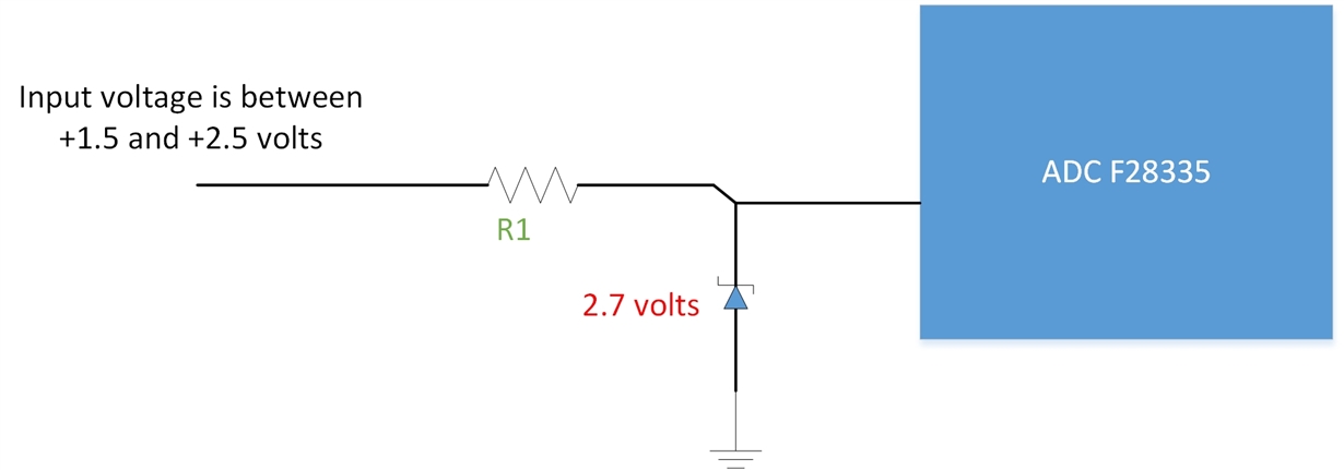
                                    I scaned the documents you suggested but most of the time they are talking about opamps. I am thinking to design my own protection circuit using zener diode for protection of ADC  port. Would you agree with the attached scheme using zener diode to keep the voltage below 3 volts for ADC input. Any advise on choosing values for resistor and zener diode. I am thinking 2.5 volts zener and i am not sure about the resistor. The DSP i am using is F28335.

    Regards, 

    Shery.

  • Hi Shery,

    For the resistor, I think you need to balance two things:

    (1) You want to limit the current through your diode if enough voltage is applied to turn on the diode.

    This should be relatively straightforward by looking at the maximum current allowed in the diode datasheet. You can use V=IR to select R such that current is sufficiently limited. Note that the effective R is the sum of both the R you place in the circuit, plus any output impedance of the of the 1.5V to 2.5V signal source. This output impedance may be negligibly small if you are using something like an op-amp, but it may be large enough that you don't need any additional resistance if the source is something high impedance like a voltage divider.

    (2) You want the ADC S+H circuit to settle in the allotted S+H time.

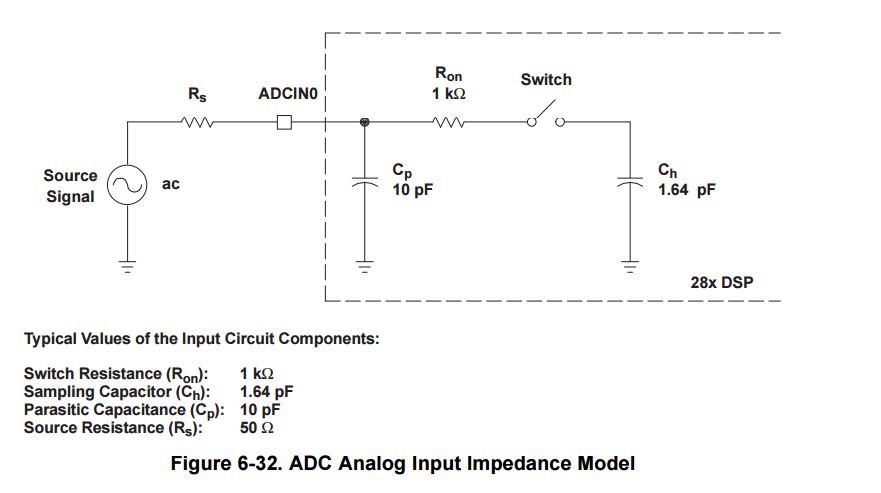
    If you look at the device datasheet in the ADC section, you will see an input model of the ADC input here:

    You want to ensure that the external source can charge Ch from 0V to within 1/4LSBs from VREFHI in the allotted S+H time. The source resistance will be whatever R value you add to the circuit before the diode, plus the source impedance of the 1.5V to 2.5V signal source.  The best way to do this is to simulate your circuit in SPICE.  Note  that a bigger R will slow down the setting, which needs to be traded off against the diode current limitation requirement. If the circuit isn't sufficiently setting, you can try some combination of reducing the R, increasing the S+H time (via the ACQ_PS setting of the ADC), or accepting some additional settling error in the application.

  • Thanks alot and beside your detailed explanation just as a plan B, would you recommend any IC which I can use in this situation, incase if my own circuit is not precise enough.
  • Hi Aero,

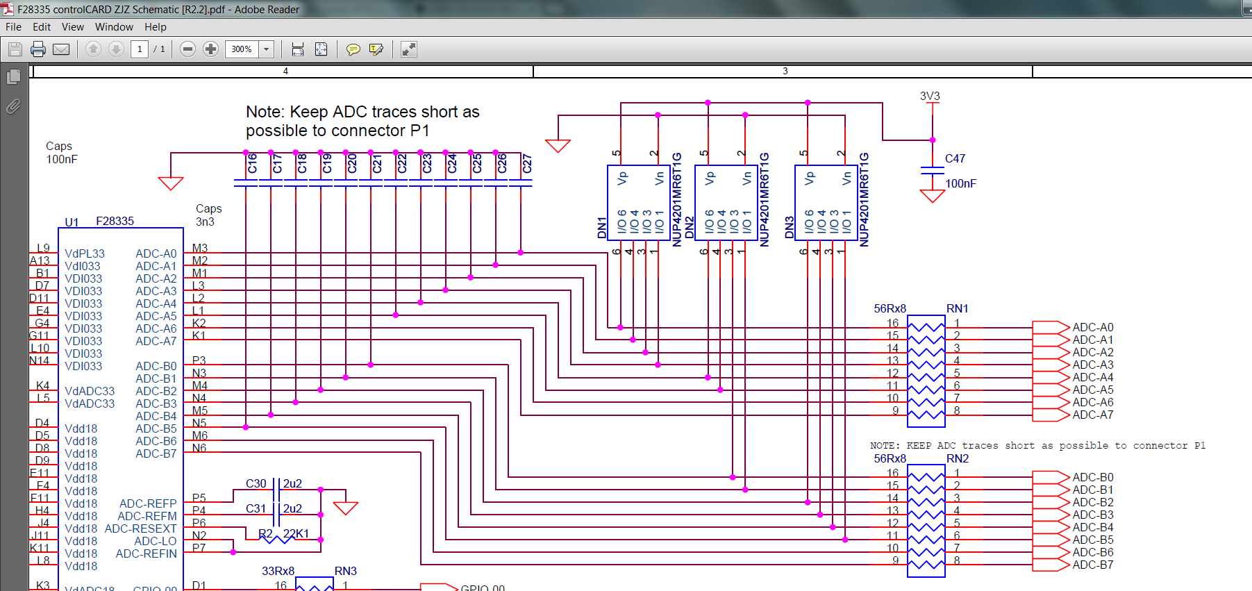
    You can always take a look a what was put on some of the development kits.  The schematics for all of this HW is somewhere in ControlSUITE in:

    ..\controlSUITE\development_kits\

    For instance, you could look at the F28335 ControlCard:

    ..\controlSUITE\development_kits\~controlCARDs\CC2833xHWdevPkg\F28335controlCARD HWDevPkg ZJZ [R2.2]

  • Thanks alot , 

                             1) How can I mange to read or visualize in the code composer what the F28335 ADC registers are reading. The goal is to be able to see what are sensor values, based on which I can design a PID controller. Can I observe whats going on in the real time on ADC on my PC.   

                             2) The input on the ADC is between 1.2 and 2.7 volts in a linear way representing linear movement of an actuator. How can I convert these values to millimeters which I need as feedback for controller design. 

    Thanks.

  • 1) Search around the CCS documentation and forum for "continuous refresh" in the expression window and the graphing tool in Tools->Graph

    2)ADC result to voltage is given by

    (adc output code/4096)*(VREFHI - VREFLO)

    e.g 3132 is equivalent to (3132/4096)*(3.0V) = 2.294V

    The formula for voltage to mm should be similar, then you can combine them and get a function for ADC code to mm and vice versa.