This thread has been locked.

If you have a related question, please click the "Ask a related question" button in the top right corner. The newly created question will be automatically linked to this question.

Complementary PWM

Hi ,

I am trying to run complimentary pair PWM's for my dc motor. I turn on and turn off the PWM's in intervals . 

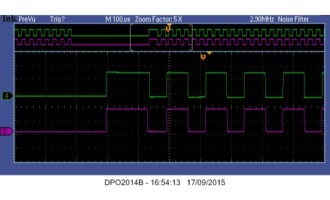
When I turn ON my PWM's , the first cycle always seems to have a longer duty cycle compared to the rest of the PWM cycles . 

Could you please tell me why this happens.

Kind Regards

Anish

  • Hi Anish,

    Try setting the correct CMPA value during peripheral configuration. Btw the above waves are not complimentary. Check the ePWM userguide or TRM for your device for proper complimentary ePWMs.

    Regards,
    Gautam
  • Hi Gautam ,
    Oh sorry , forgot to mention . These are the low phases(CMPB) of PWM1 and PWM2. I wanted to show that it was consistent. I have given the correct CMPA for the high phases and it works fine. But for my low phases is always wrong . Would there be some register that I have to reset after I turn my PWMs off ?

  • Can you share the ePWM configuration?
  • pwm_config.c
    #include "defines.h"
    #include "pwm_config.h"
    #include "global_prototypes.h"


    #define AQCTLA_INIT     0X90	
    #define AQCTLB_INIT     0X900
    #define AQCTLA_INIT_STATE ( 0x90 )
    
    #define CMPCTL_INIT_STATE ( CC_CTR_ZERO + \
                                CC_CTR_ZERO + \
                                CC_SHADOW + \
                                CC_SHADOW )
    							
    Uint16 deadband = 20;
    
    #define  PCCTL_INIT_STATE  CHP_DISABLE
    
    
    /**
     * Make the PWMs complementary with the given Phase shifts for the motors
     *
     * - The phase shifts are given with respect to PWM1 .
     */
     void
     Compl_pwm_init(struct Motor_struct *cpi_motor,
    		         Uint16 cpi_tbphs,
                     Uint16 deadband)
     {
    
     /**********************local structure pointers ***********************/
    
    	struct Local_variables *cpi_local = &cpi_motor->local;
      /**************************************************************************/
    
    	cpi_motor->phase_a.pwm->TBPRD               = cpi_local->tb_period;         /* Set timer period */
     	cpi_motor->phase_a.pwm->TBCTR               = UI_0;                         /* Clear counter */
     	cpi_motor->phase_a.pwm->TBPHS.half.TBPHS    = cpi_tbphs;                    /* Phase Offset */
     	cpi_motor->phase_a.pwm->TBCTL.all           = TB_COUNT_UPDOWN;              /* Count up and down */
     	cpi_motor->phase_a.pwm->TBCTL.bit.SYNCOSEL  = TB_SYNC_IN;                   /* Sync Output Select  (used for syncing edges for proper motor control) */
     	cpi_motor->phase_a.pwm->TBCTL.bit.PHSEN     = TB_ENABLE;                    /* Enable phase loading */
     	cpi_motor->phase_a.pwm->TBCTL.bit.HSPCLKDIV = TB_DIV1;                      /* Clock ratio to SYSCLKOUT */
     	cpi_motor->phase_a.pwm->TBCTL.bit.CLKDIV    = TB_DIV1;
     	cpi_motor->phase_a.pwm->PCCTL.all           = PCCTL_INIT_STATE;             /* Initialise PWM Chopper Control Register */
    
        /* High Resolution PWM  setup */
     	EALLOW;
     	cpi_motor->phase_a.pwm->HRCNFG.all              = UI_0;                      /* Clear all bits first.*/
     	cpi_motor->phase_a.pwm->HRCNFG.bit.EDGMODE      = UI_1;                      /* Accurately position the rising edge.*/
     	cpi_motor->phase_a.pwm->HRCNFG.bit.CTLMODE      = UI_0;                      /* Control the MEP based on the CMPAHR register. */
     	cpi_motor->phase_a.pwm->HRCNFG.bit.HRLOAD       = UI_0;                      /* Using a shadow register load when the HR counter is 0. */
     	cpi_motor->phase_a.pwm->HRPCTL.bit.TBPHSHRLOADE = UI_1;                      /* Synchronize the high-resolution phase */
     	cpi_motor->phase_a.pwm->HRPCTL.bit.HRPE         = UI_1;                      /* High resolution period enabled */
     	EDIS;
    
     	cpi_motor->phase_a.pwm->CMPCTL.all          = CMPCTL_INIT_STATE;             /* Initialise the Counter Compare Control Register */
     	cpi_motor->phase_a.pwm->AQCTLA.all          = AQCTLA_INIT_STATE;             /* Action When TBCTR = CMPA on Down Count   :  force EPWMxA output high */
                                                                                     /* Action When TBCTR = CMPA on Up Count     :  force EPWMxA output low  */
    
     	cpi_motor->phase_a.pwm->DBCTL.all           = H_11;                          /* Apath = InA (delay is by-passed for A signal path) ,  Bpath = FED (Falling Edge Delay in B signal path) */
     	                                                                             /* EPWMxB In (from the action-qualifier) is the source for rising edge delayed signal */
    
     	cpi_motor->phase_a.pwm->DBFED               = deadband;                      /* Falling Edge Delay Count */
     	cpi_motor->phase_a.pwm->DBRED               = deadband;                      /* Rising edge delay value */
     	cpi_motor->phase_a.pwm->CMPA.half.CMPA      = UI_0;
    // 	cpi_motor->phase_a.pwm->CMPB.half.CMPB       = UI_0;
    
     	cpi_motor->phase_b.pwm->TBPRD               = cpi_local->tb_period;          /* Set timer period */
     	cpi_motor->phase_b.pwm->TBCTR               = UI_0;                          /* Clear counter */
     	cpi_motor->phase_b.pwm->TBPHS.half.TBPHS    = cpi_tbphs;                     /* Phase Offset */
     	cpi_motor->phase_b.pwm->TBCTL.all           = TB_COUNT_UPDOWN;               /* Count up and down */
     	cpi_motor->phase_b.pwm->TBCTL.bit.SYNCOSEL  = TB_SYNC_IN;                    /* Sync Output Select  (used for syncing edges for proper motor control) */
     	cpi_motor->phase_b.pwm->TBCTL.bit.PHSEN     = TB_ENABLE;                     /* Enable phase loading */
     	cpi_motor->phase_b.pwm->TBCTL.bit.HSPCLKDIV = TB_DIV1;                       /* Clock ratio to SYSCLKOUT */
     	cpi_motor->phase_b.pwm->TBCTL.bit.CLKDIV    = TB_DIV1;
     	cpi_motor->phase_b.pwm->PCCTL.all           = PCCTL_INIT_STATE;              /* Initialise PWM Chopper Control Register */
    
        /* High Resolution PWM  setup */
     	EALLOW;
     	cpi_motor->phase_b.pwm->HRCNFG.all              = UI_0;                       /* Clear all bits first. */
     	cpi_motor->phase_b.pwm->HRCNFG.bit.EDGMODE      = UI_1;                       /* Accurately position the rising edge. */
     	cpi_motor->phase_b.pwm->HRCNFG.bit.CTLMODE      = UI_0;                       /* Control the MEP based on the CMPAHR register. */
     	cpi_motor->phase_b.pwm->HRCNFG.bit.HRLOAD       = UI_0;                       /* Using a shadow register load when the HR counter is 0. */
     	cpi_motor->phase_b.pwm->HRPCTL.bit.TBPHSHRLOADE = UI_1;                       /* Synchronize the high-resolution phase */
     	cpi_motor->phase_b.pwm->HRPCTL.bit.HRPE         = UI_1;                       /* High resolution period enabled */
     	EDIS;
    
     	cpi_motor->phase_b.pwm->CMPCTL.all          = CMPCTL_INIT_STATE;              /* Initialise the Counter Compare Control Register */
     	cpi_motor->phase_b.pwm->AQCTLA.all          = AQCTLA_INIT_STATE;              /* Action When TBCTR = CMPA on Down Count   :  force EPWMxA output high */
                                                                                      /* Action When TBCTR = CMPA on Up Count     :  force EPWMxA output low  */
    
     	cpi_motor->phase_b.pwm->DBCTL.all           = H_11;                           /* Apath = InA (delay is by-passed for A signal path) ,  Bpath = FED (Falling Edge Delay in B signal path) */
     	                                                                              /* EPWMxB In (from the action-qualifier) is the source for rising edge delayed signal */
    
     	cpi_motor->phase_b.pwm->DBFED               = deadband;                       /* Falling Edge Delay Count */
     	cpi_motor->phase_b.pwm->DBRED               = deadband;                       /* Rising edge delay value */
     	cpi_motor->phase_b.pwm->CMPA.half.CMPA      = UI_0;
    // 	cpi_motor->phase_b.pwm->CMPB.half.CMPB       = UI_0;
    
     	cpi_motor->phase_c.pwm->TBPRD               = cpi_local->tb_period;           /* Set timer period */
     	cpi_motor->phase_c.pwm->TBCTR               = UI_0;                           /* Clear counter */
     	cpi_motor->phase_c.pwm->TBPHS.half.TBPHS    = cpi_tbphs;                      /* Phase Offset */
     	cpi_motor->phase_c.pwm->TBCTL.all           = TB_COUNT_UPDOWN;                /* Count up and down */
     	cpi_motor->phase_c.pwm->TBCTL.bit.SYNCOSEL  = TB_SYNC_IN;                     /* Sync Output Select  (used for syncing edges for proper motor control) */
     	cpi_motor->phase_c.pwm->TBCTL.bit.PHSEN     = TB_ENABLE;                      /* Enable phase loading */
     	cpi_motor->phase_c.pwm->TBCTL.bit.HSPCLKDIV = TB_DIV1;                        /* Clock ratio to SYSCLKOUT */
     	cpi_motor->phase_c.pwm->TBCTL.bit.CLKDIV    = TB_DIV1;
     	cpi_motor->phase_c.pwm->PCCTL.all           = PCCTL_INIT_STATE;               /* Initialise PWM Chopper Control Register */
    
        /* High Resolution PWM  setup */
     	EALLOW;
     	cpi_motor->phase_c.pwm->HRCNFG.all              = UI_0;                       /* Clear all bits first. */
     	cpi_motor->phase_c.pwm->HRCNFG.bit.EDGMODE      = UI_1;                       /* Accurately position the rising edge. */
     	cpi_motor->phase_c.pwm->HRCNFG.bit.CTLMODE      = UI_0;                       /* Control the MEP based on the CMPAHR register. */
     	cpi_motor->phase_c.pwm->HRCNFG.bit.HRLOAD       = UI_0;                       /* Using a shadow register load when the HR counter is 0. */
     	cpi_motor->phase_c.pwm->HRPCTL.bit.TBPHSHRLOADE = UI_1;                       /* Synchronize the high-resolution phase */
     	cpi_motor->phase_c.pwm->HRPCTL.bit.HRPE         = UI_1;                       /* High resolution period enabled */
     	EDIS;
    
     	cpi_motor->phase_c.pwm->CMPCTL.all         = CMPCTL_INIT_STATE;               /* Initialise the Counter Compare Control Register */
     	cpi_motor->phase_c.pwm->AQCTLA.all         = AQCTLA_INIT_STATE;               /* Action When TBCTR = CMPA on Down Count   :  force EPWMxA output high */
                                                                                      /* Action When TBCTR = CMPA on Up Count     :  force EPWMxA output low  */
    
     	cpi_motor->phase_c.pwm->DBCTL.all          = H_11;                            /* Apath = InA (delay is by-passed for A signal path) ,  Bpath = FED (Falling Edge Delay in B signal path) */
     	                                                                              /* EPWMxB In (from the action-qualifier) is the source for rising edge delayed signal */
    
     	cpi_motor->phase_c.pwm->DBFED              = deadband;                        /* Falling Edge Delay Count */
     	cpi_motor->phase_c.pwm->DBRED              = deadband;                        /* Rising edge delay value */
     	cpi_motor->phase_c.pwm->CMPA.half.CMPA     = UI_0;
    // 	cpi_motor->phase_c.pwm->CMPB.half.CMPB       = UI_0;
    
     }


     /**
      *  This Function disables the complementary pair PWMs
      */
     void
     Compl_pwm_disable(struct Motor_struct *cpd_motor)
     {
    	 cpd_motor->phase_a.pwm->AQCTLA.all       = AQCTLA_INIT;        /* Action When TBCTR = CMPA on Down Count   :  force EPWMxA output high */
                                                                        /* Action When TBCTR = CMPA on Up Count     :  force EPWMxA output low  */
    
    	 cpd_motor->phase_a.pwm->AQCTLB.all       = AQCTLB_INIT;        /* Action When TBCTR = CMPB on Down Count   :  force EPWMxB output high  */
                                                                        /* Action When TBCTR = CMPB on Up Count     :  force EPWMxB output low */
    
    	 cpd_motor->phase_a.pwm->DBCTL.all        = DB_DISABLE;         /* Init Dead-Band Generator Control Register for EPWM 1*/
    	 cpd_motor->phase_a.pwm->CMPA.half.CMPA   = UI_0;
    	 cpd_motor->phase_a.pwm->CMPB.half.CMPB   = UI_0;
    
    	 cpd_motor->phase_b.pwm->AQCTLA.all       = AQCTLA_INIT;        /* Action When TBCTR = CMPA on Down Count   :  force EPWMxA output high */
                                                                        /* Action When TBCTR = CMPA on Up Count     :  force EPWMxA output low  */
    
    	 cpd_motor->phase_b.pwm->AQCTLB.all       = AQCTLB_INIT;        /* Action When TBCTR = CMPB on Down Count   :  force EPWMxB output high  */
                                                                        /* Action When TBCTR = CMPB on Up Count     :  force EPWMxB output low */
    
    	 cpd_motor->phase_b.pwm->DBCTL.all        = DB_DISABLE;         /* Init Dead-Band Generator Control Register for EPWM 2*/
    	 cpd_motor->phase_b.pwm->CMPA.half.CMPA   = UI_0;
    	 cpd_motor->phase_b.pwm->CMPB.half.CMPB   = UI_0;
    
    	 cpd_motor->phase_c.pwm->AQCTLA.all       = AQCTLA_INIT;        /* Action When TBCTR = CMPA on Down Count   :  force EPWMxA output high */
                                                                        /* Action When TBCTR = CMPA on Up Count     :  force EPWMxA output low  */
    
    	 cpd_motor->phase_c.pwm->AQCTLB.all       = AQCTLB_INIT;        /* Action When TBCTR = CMPB on Down Count   :  force EPWMxB output high  */
                                                                        /* Action When TBCTR = CMPB on Up Count     :  force EPWMxB output low */
    
    	 cpd_motor->phase_c.pwm->DBCTL.all        = DB_DISABLE;         /* Init Dead-Band Generator Control Register for EPWM 3*/
    
    	 cpd_motor->phase_c.pwm->CMPA.half.CMPA   = UI_0;
    	 cpd_motor->phase_c.pwm->CMPB.half.CMPB   = UI_0;
    
    	 cpd_motor->local.pwm_state = DISABLED;
     }
    
    
     /**
      *  This function initialises the complementary pair PWMs
      */
     void
     Comp_pwm_enable(struct Motor_struct *cpe_motor)
     {
    	 cpe_motor->phase_a.pwm->AQCTLA.all = AQCTLA_INIT;        /* Action When TBCTR = CMPA on Down Count   :  force EPWMxA output high */
                                                                  /* Action When TBCTR = CMPA on Up Count     :  force EPWMxA output low  */
    
    	 cpe_motor->phase_a.pwm->DBCTL.all  = H_11;               /* Apath = InA (delay is by-passed for A signal path) ,  Bpath = FED (Falling Edge Delay in B signal path) */
                                                                  /* EPWMxB In (from the action-qualifier) is the source for rising edge delayed signal */
    
    	 cpe_motor->phase_b.pwm->AQCTLA.all = AQCTLA_INIT;        /* Action When TBCTR = CMPA on Down Count   :  force EPWMxA output high */
                                                                  /* Action When TBCTR = CMPA on Up Count     :  force EPWMxA output low  */
    
    	 cpe_motor->phase_b.pwm->DBCTL.all  = H_11;               /* Apath = InA (delay is by-passed for A signal path) ,  Bpath = FED (Falling Edge Delay in B signal path) */
                                                                  /* EPWMxB In (from the action-qualifier) is the source for rising edge delayed signal */
    
    	 cpe_motor->phase_c.pwm->AQCTLA.all = AQCTLA_INIT;        /* Action When TBCTR = CMPA on Down Count   :  force EPWMxA output high */
                                                                  /* Action When TBCTR = CMPA on Up Count     :  force EPWMxA output low  */
    
    	 cpe_motor->phase_c.pwm->DBCTL.all  = H_11;               /* Apath = InA (delay is by-passed for A signal path) ,  Bpath = FED (Falling Edge Delay in B signal path) */
                                                                  /* EPWMxB In (from the action-qualifier) is the source for rising edge delayed signal */
    
    	 cpe_motor->local.pwm_state = ENABLED;
     }


    Please find my configuration in the attached file .

  • Hi .
    Please find my configuration below :

    #include "defines.h"
    #include "pwm_config.h"
    #include "global_prototypes.h"


    #define AQCTLA_INIT     0X90	
    #define AQCTLB_INIT     0X900
    #define AQCTLA_INIT_STATE ( 0x90 )
    
    #define CMPCTL_INIT_STATE ( CC_CTR_ZERO + \
                                CC_CTR_ZERO + \
                                CC_SHADOW + \
                                CC_SHADOW )
    							
    Uint16 deadband = 20;
    
    #define  PCCTL_INIT_STATE  CHP_DISABLE
    
    
    /**
     * Make the PWMs complementary with the given Phase shifts for the motors
     *
     * - The phase shifts are given with respect to PWM1 .
     */
     void
     Compl_pwm_init(struct Motor_struct *cpi_motor,
    		         Uint16 cpi_tbphs,
                     Uint16 deadband)
     {
    
     /**********************local structure pointers ***********************/
    
    	struct Local_variables *cpi_local = &cpi_motor->local;
      /**************************************************************************/
    
    	cpi_motor->phase_a.pwm->TBPRD               = cpi_local->tb_period;         /* Set timer period */
     	cpi_motor->phase_a.pwm->TBCTR               = UI_0;                         /* Clear counter */
     	cpi_motor->phase_a.pwm->TBPHS.half.TBPHS    = cpi_tbphs;                    /* Phase Offset */
     	cpi_motor->phase_a.pwm->TBCTL.all           = TB_COUNT_UPDOWN;              /* Count up and down */
     	cpi_motor->phase_a.pwm->TBCTL.bit.SYNCOSEL  = TB_SYNC_IN;                   /* Sync Output Select  (used for syncing edges for proper motor control) */
     	cpi_motor->phase_a.pwm->TBCTL.bit.PHSEN     = TB_ENABLE;                    /* Enable phase loading */
     	cpi_motor->phase_a.pwm->TBCTL.bit.HSPCLKDIV = TB_DIV1;                      /* Clock ratio to SYSCLKOUT */
     	cpi_motor->phase_a.pwm->TBCTL.bit.CLKDIV    = TB_DIV1;
     	cpi_motor->phase_a.pwm->PCCTL.all           = PCCTL_INIT_STATE;             /* Initialise PWM Chopper Control Register */
    
        /* High Resolution PWM  setup */
     	EALLOW;
     	cpi_motor->phase_a.pwm->HRCNFG.all              = UI_0;                      /* Clear all bits first.*/
     	cpi_motor->phase_a.pwm->HRCNFG.bit.EDGMODE      = UI_1;                      /* Accurately position the rising edge.*/
     	cpi_motor->phase_a.pwm->HRCNFG.bit.CTLMODE      = UI_0;                      /* Control the MEP based on the CMPAHR register. */
     	cpi_motor->phase_a.pwm->HRCNFG.bit.HRLOAD       = UI_0;                      /* Using a shadow register load when the HR counter is 0. */
     	cpi_motor->phase_a.pwm->HRPCTL.bit.TBPHSHRLOADE = UI_1;                      /* Synchronize the high-resolution phase */
     	cpi_motor->phase_a.pwm->HRPCTL.bit.HRPE         = UI_1;                      /* High resolution period enabled */
     	EDIS;
    
     	cpi_motor->phase_a.pwm->CMPCTL.all          = CMPCTL_INIT_STATE;             /* Initialise the Counter Compare Control Register */
     	cpi_motor->phase_a.pwm->AQCTLA.all          = AQCTLA_INIT_STATE;             /* Action When TBCTR = CMPA on Down Count   :  force EPWMxA output high */
                                                                                     /* Action When TBCTR = CMPA on Up Count     :  force EPWMxA output low  */
    
     	cpi_motor->phase_a.pwm->DBCTL.all           = H_11;                          /* Apath = InA (delay is by-passed for A signal path) ,  Bpath = FED (Falling Edge Delay in B signal path) */
     	                                                                             /* EPWMxB In (from the action-qualifier) is the source for rising edge delayed signal */
    
     	cpi_motor->phase_a.pwm->DBFED               = deadband;                      /* Falling Edge Delay Count */
     	cpi_motor->phase_a.pwm->DBRED               = deadband;                      /* Rising edge delay value */
     	cpi_motor->phase_a.pwm->CMPA.half.CMPA      = UI_0;
    // 	cpi_motor->phase_a.pwm->CMPB.half.CMPB       = UI_0;
    
     	cpi_motor->phase_b.pwm->TBPRD               = cpi_local->tb_period;          /* Set timer period */
     	cpi_motor->phase_b.pwm->TBCTR               = UI_0;                          /* Clear counter */
     	cpi_motor->phase_b.pwm->TBPHS.half.TBPHS    = cpi_tbphs;                     /* Phase Offset */
     	cpi_motor->phase_b.pwm->TBCTL.all           = TB_COUNT_UPDOWN;               /* Count up and down */
     	cpi_motor->phase_b.pwm->TBCTL.bit.SYNCOSEL  = TB_SYNC_IN;                    /* Sync Output Select  (used for syncing edges for proper motor control) */
     	cpi_motor->phase_b.pwm->TBCTL.bit.PHSEN     = TB_ENABLE;                     /* Enable phase loading */
     	cpi_motor->phase_b.pwm->TBCTL.bit.HSPCLKDIV = TB_DIV1;                       /* Clock ratio to SYSCLKOUT */
     	cpi_motor->phase_b.pwm->TBCTL.bit.CLKDIV    = TB_DIV1;
     	cpi_motor->phase_b.pwm->PCCTL.all           = PCCTL_INIT_STATE;              /* Initialise PWM Chopper Control Register */
    
        /* High Resolution PWM  setup */
     	EALLOW;
     	cpi_motor->phase_b.pwm->HRCNFG.all              = UI_0;                       /* Clear all bits first. */
     	cpi_motor->phase_b.pwm->HRCNFG.bit.EDGMODE      = UI_1;                       /* Accurately position the rising edge. */
     	cpi_motor->phase_b.pwm->HRCNFG.bit.CTLMODE      = UI_0;                       /* Control the MEP based on the CMPAHR register. */
     	cpi_motor->phase_b.pwm->HRCNFG.bit.HRLOAD       = UI_0;                       /* Using a shadow register load when the HR counter is 0. */
     	cpi_motor->phase_b.pwm->HRPCTL.bit.TBPHSHRLOADE = UI_1;                       /* Synchronize the high-resolution phase */
     	cpi_motor->phase_b.pwm->HRPCTL.bit.HRPE         = UI_1;                       /* High resolution period enabled */
     	EDIS;
    
     	cpi_motor->phase_b.pwm->CMPCTL.all          = CMPCTL_INIT_STATE;              /* Initialise the Counter Compare Control Register */
     	cpi_motor->phase_b.pwm->AQCTLA.all          = AQCTLA_INIT_STATE;              /* Action When TBCTR = CMPA on Down Count   :  force EPWMxA output high */
                                                                                      /* Action When TBCTR = CMPA on Up Count     :  force EPWMxA output low  */
    
     	cpi_motor->phase_b.pwm->DBCTL.all           = H_11;                           /* Apath = InA (delay is by-passed for A signal path) ,  Bpath = FED (Falling Edge Delay in B signal path) */
     	                                                                              /* EPWMxB In (from the action-qualifier) is the source for rising edge delayed signal */
    
     	cpi_motor->phase_b.pwm->DBFED               = deadband;                       /* Falling Edge Delay Count */
     	cpi_motor->phase_b.pwm->DBRED               = deadband;                       /* Rising edge delay value */
     	cpi_motor->phase_b.pwm->CMPA.half.CMPA      = UI_0;
    // 	cpi_motor->phase_b.pwm->CMPB.half.CMPB       = UI_0;
    
     	cpi_motor->phase_c.pwm->TBPRD               = cpi_local->tb_period;           /* Set timer period */
     	cpi_motor->phase_c.pwm->TBCTR               = UI_0;                           /* Clear counter */
     	cpi_motor->phase_c.pwm->TBPHS.half.TBPHS    = cpi_tbphs;                      /* Phase Offset */
     	cpi_motor->phase_c.pwm->TBCTL.all           = TB_COUNT_UPDOWN;                /* Count up and down */
     	cpi_motor->phase_c.pwm->TBCTL.bit.SYNCOSEL  = TB_SYNC_IN;                     /* Sync Output Select  (used for syncing edges for proper motor control) */
     	cpi_motor->phase_c.pwm->TBCTL.bit.PHSEN     = TB_ENABLE;                      /* Enable phase loading */
     	cpi_motor->phase_c.pwm->TBCTL.bit.HSPCLKDIV = TB_DIV1;                        /* Clock ratio to SYSCLKOUT */
     	cpi_motor->phase_c.pwm->TBCTL.bit.CLKDIV    = TB_DIV1;
     	cpi_motor->phase_c.pwm->PCCTL.all           = PCCTL_INIT_STATE;               /* Initialise PWM Chopper Control Register */
    
        /* High Resolution PWM  setup */
     	EALLOW;
     	cpi_motor->phase_c.pwm->HRCNFG.all              = UI_0;                       /* Clear all bits first. */
     	cpi_motor->phase_c.pwm->HRCNFG.bit.EDGMODE      = UI_1;                       /* Accurately position the rising edge. */
     	cpi_motor->phase_c.pwm->HRCNFG.bit.CTLMODE      = UI_0;                       /* Control the MEP based on the CMPAHR register. */
     	cpi_motor->phase_c.pwm->HRCNFG.bit.HRLOAD       = UI_0;                       /* Using a shadow register load when the HR counter is 0. */
     	cpi_motor->phase_c.pwm->HRPCTL.bit.TBPHSHRLOADE = UI_1;                       /* Synchronize the high-resolution phase */
     	cpi_motor->phase_c.pwm->HRPCTL.bit.HRPE         = UI_1;                       /* High resolution period enabled */
     	EDIS;
    
     	cpi_motor->phase_c.pwm->CMPCTL.all         = CMPCTL_INIT_STATE;               /* Initialise the Counter Compare Control Register */
     	cpi_motor->phase_c.pwm->AQCTLA.all         = AQCTLA_INIT_STATE;               /* Action When TBCTR = CMPA on Down Count   :  force EPWMxA output high */
                                                                                      /* Action When TBCTR = CMPA on Up Count     :  force EPWMxA output low  */
    
     	cpi_motor->phase_c.pwm->DBCTL.all          = H_11;                            /* Apath = InA (delay is by-passed for A signal path) ,  Bpath = FED (Falling Edge Delay in B signal path) */
     	                                                                              /* EPWMxB In (from the action-qualifier) is the source for rising edge delayed signal */
    
     	cpi_motor->phase_c.pwm->DBFED              = deadband;                        /* Falling Edge Delay Count */
     	cpi_motor->phase_c.pwm->DBRED              = deadband;                        /* Rising edge delay value */
     	cpi_motor->phase_c.pwm->CMPA.half.CMPA     = UI_0;
    // 	cpi_motor->phase_c.pwm->CMPB.half.CMPB       = UI_0;
    
     }


     /**
      *  This Function disables the complementary pair PWMs
      */
     void
     Compl_pwm_disable(struct Motor_struct *cpd_motor)
     {
    	 cpd_motor->phase_a.pwm->AQCTLA.all       = AQCTLA_INIT;        /* Action When TBCTR = CMPA on Down Count   :  force EPWMxA output high */
                                                                        /* Action When TBCTR = CMPA on Up Count     :  force EPWMxA output low  */
    
    	 cpd_motor->phase_a.pwm->AQCTLB.all       = AQCTLB_INIT;        /* Action When TBCTR = CMPB on Down Count   :  force EPWMxB output high  */
                                                                        /* Action When TBCTR = CMPB on Up Count     :  force EPWMxB output low */
    
    	 cpd_motor->phase_a.pwm->DBCTL.all        = DB_DISABLE;         /* Init Dead-Band Generator Control Register for EPWM 1*/
    	 cpd_motor->phase_a.pwm->CMPA.half.CMPA   = UI_0;
    	 cpd_motor->phase_a.pwm->CMPB.half.CMPB   = UI_0;
    
    	 cpd_motor->phase_b.pwm->AQCTLA.all       = AQCTLA_INIT;        /* Action When TBCTR = CMPA on Down Count   :  force EPWMxA output high */
                                                                        /* Action When TBCTR = CMPA on Up Count     :  force EPWMxA output low  */
    
    	 cpd_motor->phase_b.pwm->AQCTLB.all       = AQCTLB_INIT;        /* Action When TBCTR = CMPB on Down Count   :  force EPWMxB output high  */
                                                                        /* Action When TBCTR = CMPB on Up Count     :  force EPWMxB output low */
    
    	 cpd_motor->phase_b.pwm->DBCTL.all        = DB_DISABLE;         /* Init Dead-Band Generator Control Register for EPWM 2*/
    	 cpd_motor->phase_b.pwm->CMPA.half.CMPA   = UI_0;
    	 cpd_motor->phase_b.pwm->CMPB.half.CMPB   = UI_0;
    
    	 cpd_motor->phase_c.pwm->AQCTLA.all       = AQCTLA_INIT;        /* Action When TBCTR = CMPA on Down Count   :  force EPWMxA output high */
                                                                        /* Action When TBCTR = CMPA on Up Count     :  force EPWMxA output low  */
    
    	 cpd_motor->phase_c.pwm->AQCTLB.all       = AQCTLB_INIT;        /* Action When TBCTR = CMPB on Down Count   :  force EPWMxB output high  */
                                                                        /* Action When TBCTR = CMPB on Up Count     :  force EPWMxB output low */
    
    	 cpd_motor->phase_c.pwm->DBCTL.all        = DB_DISABLE;         /* Init Dead-Band Generator Control Register for EPWM 3*/
    
    	 cpd_motor->phase_c.pwm->CMPA.half.CMPA   = UI_0;
    	 cpd_motor->phase_c.pwm->CMPB.half.CMPB   = UI_0;
    
    	 cpd_motor->local.pwm_state = DISABLED;
     }
    
    
     /**
      *  This function initialises the complementary pair PWMs
      */
     void
     Comp_pwm_enable(struct Motor_struct *cpe_motor)
     {
    	 cpe_motor->phase_a.pwm->AQCTLA.all = AQCTLA_INIT;        /* Action When TBCTR = CMPA on Down Count   :  force EPWMxA output high */
                                                                  /* Action When TBCTR = CMPA on Up Count     :  force EPWMxA output low  */
    
    	 cpe_motor->phase_a.pwm->DBCTL.all  = H_11;               /* Apath = InA (delay is by-passed for A signal path) ,  Bpath = FED (Falling Edge Delay in B signal path) */
                                                                  /* EPWMxB In (from the action-qualifier) is the source for rising edge delayed signal */
    
    	 cpe_motor->phase_b.pwm->AQCTLA.all = AQCTLA_INIT;        /* Action When TBCTR = CMPA on Down Count   :  force EPWMxA output high */
                                                                  /* Action When TBCTR = CMPA on Up Count     :  force EPWMxA output low  */
    
    	 cpe_motor->phase_b.pwm->DBCTL.all  = H_11;               /* Apath = InA (delay is by-passed for A signal path) ,  Bpath = FED (Falling Edge Delay in B signal path) */
                                                                  /* EPWMxB In (from the action-qualifier) is the source for rising edge delayed signal */
    
    	 cpe_motor->phase_c.pwm->AQCTLA.all = AQCTLA_INIT;        /* Action When TBCTR = CMPA on Down Count   :  force EPWMxA output high */
                                                                  /* Action When TBCTR = CMPA on Up Count     :  force EPWMxA output low  */
    
    	 cpe_motor->phase_c.pwm->DBCTL.all  = H_11;               /* Apath = InA (delay is by-passed for A signal path) ,  Bpath = FED (Falling Edge Delay in B signal path) */
                                                                  /* EPWMxB In (from the action-qualifier) is the source for rising edge delayed signal */
    
    	 cpe_motor->local.pwm_state = ENABLED;
     }


  • Hi Anish,

    I believe the waveform is for the PWMB output. Correct?
    What is the initial value of CMPB? Can you try a non-zero value?

    -Bharathi.

  • Hi Bharathi , 

    Yes it is for PWMB output . 

    The initial value is zero . I did try giving 650 and  1250  , but the motor draws more current and doesnt turn .