This thread has been locked.

If you have a related question, please click the "Ask a related question" button in the top right corner. The newly created question will be automatically linked to this question.

How to get USB flash kernel working for 28377D CPU2?

Expert 1960 points
Other Parts Discussed in Thread: CONTROLSUITE, TMS320F28377D, SYSBIOS

Hi Folks,

I've the usb flash kernel example working for CPU1 (thanks to the help of Sal!). Now I try to get it work for CPU2. I rebuilt the usb_flash_kernels_cpu01.dat with "DUAL" defined, and then successfully loaded the rebuilt CPU1 kernel and blinky_dc_cpu01 with usb_flash_programmer.exe. Then I continued to load usb_flash_kernels_cpu02.dat successfuly. Then I tried to load blinky_dc_cpu02.dat, but it failed. Has anyone got this working, and please share some tips on troubleshooting? 

I also tried rebuilt usb_flash_programmer on my win7 to help debugging. I installed VS2010 and Windows Device Kit 8.0 and 8.1 update packages. But it still complains about missing winusb.h. I searched WDK install folder in Program Files (x86) but could not find it either. What else do I need to install on Win7 in order to get it rebuilt? Many thanks in advance for your help!

  • CPU2 can't access the USB module. You'll have to pass the data through CPU1 via the IPC RAM.

    The version of WinUSB that we use comes from WDK 7.1. Try downloading it here:

    www.microsoft.com/.../details.aspx
  • Hi Adam,
    Thank for your link to the WDK 7.1. I installed it and got the usb_flash_programmer built now. Apparently Microsoft has decided to remove winusb.lib from its later WDK releases, 8 and 8.1?
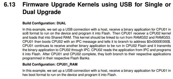
    I know that CPU2 does not have access to USB, and has to use IPC RAM to get it from CPU1. That's why I rebuilt usb_flash_kernels_cpu01.dat in DUAL mode, and assumed that it will help to load application for CPU2, as described in the "2837xD Firmware Dev Package Users Guide", Section 6.13 "Firmware Upgrade Kernels using USB for Single or Dual Upgrade", as shown below. I noticed that in F2837xD_use_flash_kernels_cpu01 project folder, there is another cmd file called flash_programming_cpu1tocpu2_RAM.cmd, which was excluded in single-core mode (DUAL not defined). So I used it to rebuild the cpu01 kernel with DUAL defined.

    Is there anything else needed in order to get this example project working? Please advise. Thanks!
  • Shef,

    It sounds like you have successfully loaded the CPU kernel into shared RAM. Have you confirmed this? How?

    Can you connect to CPU1 and CPU2 when the programming apparently fails, and see where the PC is and the code is running from please? After it apparently fails, connect via JTAG to the two C28x cores and load the kernel symbols. This will show you what the cpu is doing.

    sal
  • Hi Sal,
    Thanks for your reply. Yes I did get the CPU1 kernel working, thanks to your earlier help. It seems that I had to get boot ROM working first, and let the Win7 to pick up the correct windows driver. After that, I loaded the cpu1 kernel project, and it worked too! I confirmed with -l to check device, and also successfully loaded blinky into CPU1 flash and saw it blinking after power on/off.

    I then moved on to get CPU2 working. Here is the steps I took:
    1) Rebuilt CPU1 kernel using flash_programming_cpu1tocpu2_RAM.cmd, and exclude flash_programming_cpu1_RAM.cmd.
    2) Load and run the CPU1 kernel from debugger, and verify with -l to see it's working.
    3) usb_flash_programmer.exe blinky_dc_cpu1.dat, success.
    4) usb_flash_programmer.exe F2837xD_usb_flash_kernels_cpu02.dat - success!
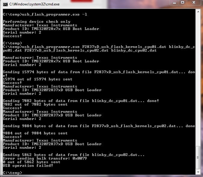
    5) usb_flash_programmer.exe blinky_dc_cpu2.dat. Failed. Error message:
    Sending 5680 bytes of data from file blinky_dc_cpu02.dat...
    Error sending bulk transfer: 0x0079
    0 out of 5680 bytes sent
    USB operation failed!

    On CCS debugger, it stuck at cpu01 kernel -> USB_Boot.c::USB_Boot2()::Line 178 wait; // entry address.
    It looks like that it's waiting for IPC response?

    I just used the original example in controlSuite v160, without any change in source code or anything. But I do have to copy over the source files to rebuild the project since the links to files are all invalid and failed to build.

    Please advise what I can do next to get this to work. Thanks!
  • Have you tried to set the EMU boot mode to USB boot, resetting the device, and then using the usb_flash_programmer to load all 4 executables?
    Try programming your device in standalone mode.

    It seems as if the CPU2 kernel is not operating properly and has not been booted to correctly. Can you connect to CPU2 and load symbols and see where it is stuck?

    sal
  • Hi Sal,
    One more piece of info. The fw upgrade example in controlSuite ~Utilities folder only has blinky binary for cpu1, and I cannot find any flash example to use for cpu2. So I rebuilt dual blinky_dc example in F2837xD_examples_Dual, by replacing RAM cmd with Flash cmd file. I manually tested them both by loading them into cpu1 and 2 with debugger, and got them working in parallel. I had to set 0B5A in 0xD00 of cpu2 in order to run it from flash, otherwise it won't run after power-on.

    I also converted them to bootloader .dat file and tried to load via usb_flash_programmer.exe. But only works for cpu01, not cpu2. That's when I started to post the issue here. Can you or someone else in TI got an example working for cpu2? If so can you send me the example and steps to try? Many thanks to you all for looking into it.
  • There should be a Build Configuration for Flash for the blinky_dc example.  Right click on the project and find Build Configurations.

    You should not have to change the Boot mode of CPU2 at 0xD00.  Did you Run CPU1 first then CPU2?  You should Run CPU2 first, which will wait for an IPC command from CPU1, and then Run CPU1.

    Please try this first. I will post in a little bit after getting the dual core usb_flash_programmer working.

    sal

  • Shef,

    I think this is the problem. You need to set the F2837xD_usb_flash_kernels_cpu01 Build Configuration of the project to DUAL.

    There are different build configurations for these kernels depending on if you are trying to flash CPU01 or both Cores. Set the Build Configuration to DUAL and then recompile and convert the executable to the appropriate hex file to load to the bootloader.

    sal
  • Hi Sal,
    Thanks for the info different build config. I rebuilt both blinky_dc_cpu1, blinky_dc_cpu2 in CPUx_FLASH config, and then I rebuilt F2837xD_usb_flash_kernels_cpu01 in DUAL config. For F2837xD_usb_flash_kernels_cpu02, there is only one config called CPU2_RAM. Then I tried the same steps as described in my earlier post (Sep 26, 2015 4:48 AM). Sadly I got the same thing. This is not a surprise since previously I've already rebuilt the same thing. I did not use the preconfiged DUAL mode, but I added DUAL as a symbol, and replaced cmd file with the other one. This is basically what the preconfigured DUAL mode does.

    It sounds like that you've already got the CPU2 working on your PC. Can you describe the exact steps you took, and what source code did you use? For example, when and how did you load the CPU1 kernel (DUAL), with debugger or with boot ROM? When and how did you load CPU2 kernel into CPU2? I suppose that we have to load both CPU1 & CPU2 kernels before we can load blinky_cpu02. So I'm not exactly sure what you meant by "you have to run CPU2 first" in earlier post. So, some detailed steps/scripts would help a lot since there is no formal documentation on how to do it for CPU2. Many thanks and I do appreciate your timely help. I look forward to your next post.
  • Shef,

    I am experiencing the same issue. I will need some time to debug this and will get back to you by the end of the week.

    If you try to debug this as well, you can load symbols and see where the C28x cores are running.

    sal
  • Right now CPU1 is stuck at line 178 of USB_Boot.c You may have already said this above. The line of code is "wait;"

    It seems as if CPU2 is not booting properly to the CPU2 kernel in shared memory and is therefore not communicating via IPC to CPU1.

    sal
  • Shef,

    I was able to get both kernels loaded and both flash applications programmed. I did not have to change the code.

    You can debug the code by adding symbols of the kernels and the bootROM symbols which are in controlSUITE.

    Here are the steps.
    1) Launch Target Configuration File
    2) Connect to CPU1 only
    3) write 0x0C5A to location 0xD00
    4) do a debugger reset
    5) Run CPU1
    6) disconnect CPU1
    7) run usb_flashprogrammer
    :> usb_flash_programmer <cpu1_kernel> <cpu1_flash_application> <cpu2_kernel> <cpu2_flash_application>

    Let me know if this works. If it does not, send me some details so I can help you debug further.

    sal
  • Hi Sal,
    I see hope when I heard that you've got it working on your side! Thanks for your detailed steps. I did exactly as you described, and it went well from step 1-6, and most of step 7, but failed at the last file blinky_dc_cpu02.dat, after it loaded successfully 3 other files (i.e. CPU1 kernel in DUAL mode, blinky_dc_cpu01.dat and CPU2 kernel). THen I reconnected debugger, and found that CPU stuck at line 178 (wait). I also loaded CPU2 kernel symbols for CPU2, it says "No symbols are defined for 0x3fec52", presumably in boot ROM. But I searched controlSuite, could bot find symbols file for CPU2 boot ROM. Can you tell me the folder name for bootROM symbols?

    I'll try to upload a screenshot soon.
  • screenshot for PC side:

  • Hi Sal,
    How are you doing? You mentioned that you initially had the same issue and CPU1 stuck at line 178 (wait). How did you get it resolved? Since I went through all steps except Step 7, would you mind sending me the 4 downloadable files (.dat) that you used. If they work fine on my hardware, we can focus on the .dat file generating. Hopefully I'll get this resolved soon, with your help. Thanks again!
  • BootRom symbols:  C:\ti\controlSUITE\libs\utilities\boot_rom\F2837x_revb\revb_rom_sources\ccs_files

    I got it working by just trying it again a few times.

    Try these.  They should be the same that you have.

    saldual.zip

  • Hi Sal,

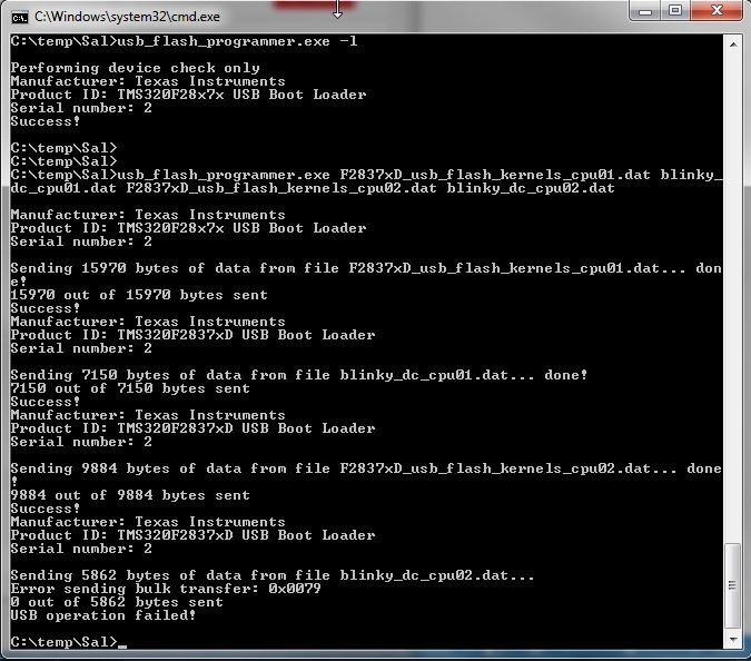
    Thanks for the .dat files. They have slightly different sizes from what I have, but not much. I copied your files into a different folder and started with a brand new EVM 377D board, and followed your 7-step instruction earlier. Then I got the same thing as I got earlier, i.e. it went well all the way from step 1-7, but failed at the last file blinky_dc_cpu02.dat). Please see the attached screenshot below. If you compare it with your result, e.g. product ID etc, do you see any clue?

  • Shef,

    Here is a suggestion. In the CPU1 kernel, after loading the CPU1 application and the CPU2 kernel, add a CPU2 Reset. Reset CPU2 from CPU1 kernel inside the #ifdef DUAL before the while loop getting the IPCGetBootStatus().

    Check the TRM for specific details, but you will need to write to CPU2RESCTL
    pseduo code:

    CPU2RESCTL = 0xA5A50001;
    RPT 3 | NOP
    CPU2RESCTL = 0xA5A50000;

    This should make sure CPU2 is coming straight out of reset before starting the IPC communication.

    sal
  • Shef,

    Do you have this working yet??

    sal
  • Hi Sal,
    Thanks for asking. No I have not got it working yet. I looked at the TRM but couldn't figure out how to set CPU2RESCTL in order to reset CPU2. I'm kinda new to this MCU, and assumed that the examples provided in controlSuite would just work without much effort. But it sounds like that the example may still need some work. In that case, would you mind trying the suggested solution on your side, which would be much quicker to see if it works or not. I'd be happy to test your revised code to get CPU2 working. This would help everyone else too. Thanks for your help this far and hopefully we will get this resolved soon.
  • Hi Shef,

    CPU2RECTL is in the DEV_CFG_REGS Registers set.  

    I will attempt to get this implemented by the end of the week.  Thank you for your patience.

    sal

  • Thank you Sal! I look forward to your fix. That'll make many people out of there happy with TI!
    You mentioned that you got the same error on your side too sometimes, but somehow failed 100% on mine.
    We need to get it working reliably for a product in the field, which cannot afford any failure.
    Thanks again for your help - really appreciated!
  • Hi Sal,

    I was wondering if you had a chance to get it working? You mentioned that you'd implement it by end of the week, so I thought I was anxious to try it out. But please take your time if it turns out to be more challenging than expected. Thanks again!
  • dual2.zipShef,

    Please try this.

    Add the first 3 lines of code to the CPU1 project.

    DevCfgRegs.CPU2RESCTL.all = 0xA5A50001;
    __asm(" RPT #5 || NOP");
    DevCfgRegs.CPU2RESCTL.all = 0xA5A50000;

    while (1)
    {
    uint32_t bootStatus = IPCGetBootStatus() & 0x0000000F;
    if (bootStatus == C2_BOOTROM_BOOTSTS_SYSTEM_READY)
    break;
    else if (bootStatus == C2_BOOTROM_BOOTSTS_C2TOC1_BOOT_CMD_ACK)//if CPU2 is already booted, then fail
    Example_Error(Fapi_Error_Fail);
    }

    Let me know if this works.

    sal

  • Hi Sal,
    THANK YOU SO MUCH! You are a true guru and your solution works!
    However, not sure if you saw the same thing as I did, there are still some minor issues observed my side:
    1) The command-line with all 4 dat file together (as you suggested earlier) does not work on some EVM boards, but works fine on some other boards. Not sure why. Is it related to Boot ROM revision at all? I also saw similar issues with usb serial example, which works fine on some boards, but not on others. Any idea why?
    2) When I run command with single dat file one by one, it works fine with all 4 files, and both CPUs run blinky example.
    3) When I run usb_kernel_cpu01 from debugger, and then run usb_flash_programer.exe with 3 dat files, it also work fine. This is great news since I can customize usb kernel if needed.
    Anyway, thanks again for your help!!
  • Good to hear!

    I have not seen different behavior between devices. I think I have only used Rev B.

    What Revision of the F2837x cCard are you using?

    Please verify the above response. This will also close the thread. We can continue discussing here even if the thread is closed.

    sal
  • Hi Sal again,
    All my cCard is labelled as F2837x R1.1, although they were purchased at different times. I checked the location 0x3FFF7A, one has 0101 0114, and the other one has 0100 0413. Both have the same issue. I'll check more cards later if this makes difference.
  • Hi Sal,
    FYI, I just checked another cCard, which also has 0101 0114 at OTP location 0x3FFF7A. This one works fine when I run usb_flash_programmer.exe with all 4 dat files. But the other one does not work (which was purchased at the same time and has the same ROM revsion info). They all Rev B from the chip label and RevID in 5D00C (shown as 0002). Any idea why and how to troubleshoot it? Thanks!
  • Hi Sal,
    FYI, I just checked another cCard, which also has 0101 0114 at OTP location 0x3FFF7A. This one works fine when I run usb_flash_programmer.exe with all 4 dat files. But the other one does not work (which was purchased at the same time and has the same ROM revsion info). They all Rev B from the chip label and RevID in 5D00C (shown as 0002). Any idea why and how to debug? Thanks!
  • Shef,

    Are your jumper switches configured identically on all of the cCards?

    sal
  • Shef,

    Please describe again what the behavior is that you are seeing?

    Is it true that you can always load 3 files, but the 4th hangs? Are you always able to load to CPU1 properly?

    sal
  • Hi Sal,
    I've resolved the issue that I mentioned earlier, which is occasional failure of executing usb flash programmer with all 4 files in one line. It was because that the host app did not wait long enough after sending the first file. After I increased the waiting time, it works fine now always. My next step is to find a method to force MCU to change from application mode (e.g. running blinky) to usb firmware update mode. I'm thinking to save the CPU1 kernel into flash, and then jump from application code to the CPU1 kernel once a request is received. Do you have suggestion for other ways to do this? Thanks!
  • Hi Shef,

    Good to hear!

    When you say it was "because that the host app did not wait long enough after sending the first file," do you mean the original usb_flash_programmer?? Did you have trouble with the original usb_flash_programmer and updated kernels? OR did you modify the programmer/kernels?

    They way you suggested is correct. You can save the kernels into flash and branch to them from your application in order to perform a flash upgrade. But you will need to load them from flash into RAM when performing a flash update because the Flash API must run from RAM.

    sal
  • Hi Sal,
    Yes I did modify the host app usb_flash_programmer and reduced the wait-time perhaps too short. It's ok now.
    Moving forward, I feel like to make this usb flash kernel more like original Piccolo usb bootloader which works as standard DFU. Do you know why TI does not support DFU bootloader on 377D anymore? I know that 377 has usb boot room but it's not the same as DFU and we have to write special host program to work with it from linux. Would it be easy to make DFU kernel running on 377 just as before, or is there any reason to abandon dfu on this new chip? The original dfu bootloader runs from flash, and it seems to be easy to use, with documentation etc. I'd appreciate some further info and guidance on this. Thanks!
  • We are switching to this solution because the DFU solution is not as easy to understand and implement. There are things mentioned in the document that never got implemented.

    sal
  • Hi Sal,

    Thanks again for your help so far. After getting several example .dat files loaded successfully into flash, I'm now trying to use the usb flash kernel to load our own firmware. However, it failed in CopyData() at line 114 Fapi_issueProgrammingCommand() which returns an "enum unknown". This particular firmware works fine in flash (after loading with debugger), even after power reset. I just converted it to .dat file in the same way as all other examples in CCS post-build steps. It's about 87k in size, as attached here. I used the original usb_flash_kernel to load to CPU1. CPU2 is not used here. I can send you project source code if needed. Thanks a lot for your continued support!myfirmware.dat

  • Hi Shef,

    Please explain exactly how you are using the usb_flash_programmer and the usb flash kernel.

    Have you made any modifications?
    Are you loading the kernel into RAM via the bootloader?
    Is the flash application mapped completely and only to flash? Please send me the .map file.

    sal
  • Hi Sal,
    Thanks for your quick response. I used the original usb_flash_programmer & usb flash kernel without any modification. I first tried loading the kernel with boot ROM. Then I load the CPU1 kernel via CCS, so that I could see where it stopped.
    However, my flash app is NOT mapped completely and only to flash. It has some small functions mapped into RAM (ramfuncs) for better performance and self-test. It also uses sys/bios for task scheduling. Have you or someone in TI test the flash kernel with a more realistic flash app like mine? If not, I'd be happy to work with you guys to get this working, so that this can be more useful for real products like ours. Many thanks again!
  • Hi Shef,

    The flash kernel expects that the data loaded via the usb is completely a flash application. This is typically the use case.

    If your board ever loses power or fails, it will lose the contents of the RAM as it is volatile memory. It is best to program the entire application into flash and perform a memcpy from flash to RAM. This is what ramfuncs are for. All code should be programmed into flash and a memcpy should be called to copy ramfuncs from flash to RAM.

    If you do not want to do this, you can modify the kernel to check the memory address of the block that is being transferred and perform a CPU write of the data to the RAM for a RAM address OR use the flash API for flash address.

    sal
  • Hello Sal,

    I tried to send you the map file via private message but it always error out. Can you give me your email address so that I can send it to you? I also send you a connection request, just to forward you more info if needed.

    I'm not sure if it's completely mapped into flash, or not. We run some functions from RAM, but the code are still loaded into Flash first. The app runs fine after we power off and on the board.

    Please let us know if you see anything wrong in the map file, so that we can correct it. Thanks!
  • Hi Sal,
    To verify, I just tried an simple unmodified sys/bios example from CCS resource explorer. It's called task_TMS320F28377D which runs in flash with a simple standard cmd file. It runs correctly from CCS. Then I convert it to .dat file and tried to load with usb flash kernel. Got exactly the same issue. It error out in CopyData and ended up in Example_Error. This is the original simple example from TI, therefore should be easy to reproduce. Can you take a look and let me know what we can do to resolve it? Thanks!
  • Shef,

    I am able to load flash applications via the usb_flash_programmer.
    What is the BlockHeader.DestAddr, and size of the buffer when you call Fapi_issueProgramingCommand() and get the error?

    Does it fail on the first call to the FAPI program function?

    In your flash application, did you align the flash sections to a 64-bit boundary? Did you use ALIGN(4) in the linker command file?

    sal
  • Hi Sal,
    It's wonderful! If it works you should see an LED blinking once per second, and logging text is spilled out from UART via SCI/USB console continuously. If this is the case, I'm anxious to know why not working on mine, a simple 377D EVM board. I've tried several boards too but all with same failure. Do you still want to see the map file?

    When it failed on mine, BlockHeader.DestAddr = 0x820F1 (532721). The error message on the host side is:

    Error sending bulk transfer: 0x0079
    0 out of 37652 bytes sent
    USB operation failed!

    But I'm not sure about your last 2 questions. I did not knowingly align the flash to a 64-bit boundary or use ALIGN(4) in linker cmd file. Please advise more if I need to do this in order to use bootloader.

    In my previous post, I mentioned that a simple TI sys/bios example also failed. It uses the standard linker cmd file called TMS320F28377D.cmd. Does it mean that we have to do something more in order to make a flash application bootable from USB flash kernel?
  • Hi Sal,
    I attach the .dat and .map file for the sys/bios task example which comes from CCS . Can you take a look to see if it loads and runs ok with your USB flash kernel? If not, you can look at the map file (attached) or the project source code from CCS resource explorer. It does not work on my side. But I tried several other simple flash examples (like blinky, sci_echoback etc, not using sys/bios) which all work fine. Thanks!
  • THis is the .map file for the above sys/bios example, but the forum does not allow it to be attached.

    So I changed it to .txt file, since it's only a plain text file anyway.

    task_TMS320F28377D.txt

  • I did not test your binary. I tested other binaries.

    In your map file .econst starts at a location which is not 64-bit aligned and I think this is the problem.

    You need to added ALIGN(4) to all of your flash sections in the linker command file. For example, .econst needs to have ", ALIGN(4)" at the end of the section in the linker command file.

    It looks like your program is failing when trying to load and program a destination address 0x820F1. This is not 64-bit aligned. Looks like you need to align .cinit.

    sal
  • Hi Sal,
    Thanks for your info on alig(4). It's indeed the problem. For this particularly example which uses sys/bios, the problem is in linker.cmd file which is automatically generated by CCS. I tried to modify it and rebuilt the project, which loaded successfully, but it then gets overwritten after I rebuild the project. THis might be a question for SYS/BIOS guys, but is there anyway to fix it in the source?

    ANother question is: you said that the flash needs to be aligned for 64-bit boundary, but suggested to use ALIG(4), which is to align 32-bit (4 bytes). Did I miss anything here, or where can I read more details on this subject? I read c28 assembly manual but not much about it. I'm totally convinced that you are a real guru who has resolved my problem every time. Thanks so much!
  • Hi Shef,

    I am not sure about the SYSBIOS project and the linker command file. You may want to post something on the SYSBIOS forum.

    We are a 16-bit word machine. Therefore, 4 x 16-bit = 64-bit.

    sal