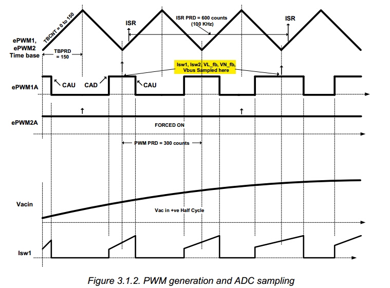
The example project is BridgelessPFC, in the BridgelessPFC-Main.c there may exist some mistakes
Line901-910
// PWM based ISR trigger
PieVectTable.EPWM1_INT = &DPL_ISR; // Map Interrupt
PieCtrlRegs.PIEIER3.bit.INTx1 = 1; // PIE level enable, Grp3 / Int1, ePWM1
EPwm1Regs.CMPB = 80; // ISR trigger point
EPwm1Regs.ETSEL.bit.INTSEL = ET_CTRU_CMPB; // INT on CompareB-Up event
EPwm1Regs.ETSEL.bit.INTEN = 1; // Enable INT
// EPwm1Regs.ETPS.bit.INTPRD = ET_1ST; // Generate INT on every event
EPwm1Regs.ETPS.bit.INTPRD = ET_2ND; // Generate INT on every event
Is this comment right?ET_1ST means Generate INT on every event,but ET_2ND means Generate INT on every other event
Line557-560
// Configure ePWMs to generate ADC SOC pulses
EPwm1Regs.ETSEL.bit.SOCAEN = 1; // Enable ePWM1 SOCA pulse
EPwm1Regs.ETSEL.bit.SOCASEL = ET_CTR_ZERO; // SOCA from ePWM1 Zero event
EPwm1Regs.ETPS.bit.SOCAPRD = ET_1ST; // Trigger ePWM1 SOCA on every event
As the project document(BLPFC_Rev1.1.pdf Page 11) introduced,
the PWM switching frequency is 200kHz, the ISR and ADC sampling frequency are 100kHz, the ISR is triggered on CompareB-Up event, and ADCSOCA from ePWM1 Zero event, but the following code:
EPwm1Regs.ETPS.bit.INTPRD = ET_2ND;
EPwm1Regs.ETPS.bit.SOCAPRD = ET_1ST;
As this configuration, the ISR frequency is 100kHz and ADC sampling frequency is 200kHz,
maybe the right configuration should be:
EPwm1Regs.ETPS.bit.INTPRD = ET_2ND;
EPwm1Regs.ETPS.bit.SOCAPRD = ET_2ND;
Is this right?


