This thread has been locked.

If you have a related question, please click the "Ask a related question" button in the top right corner. The newly created question will be automatically linked to this question.

How can i configure the memory map on C28027 Targets - Ccs 3.3

Hi


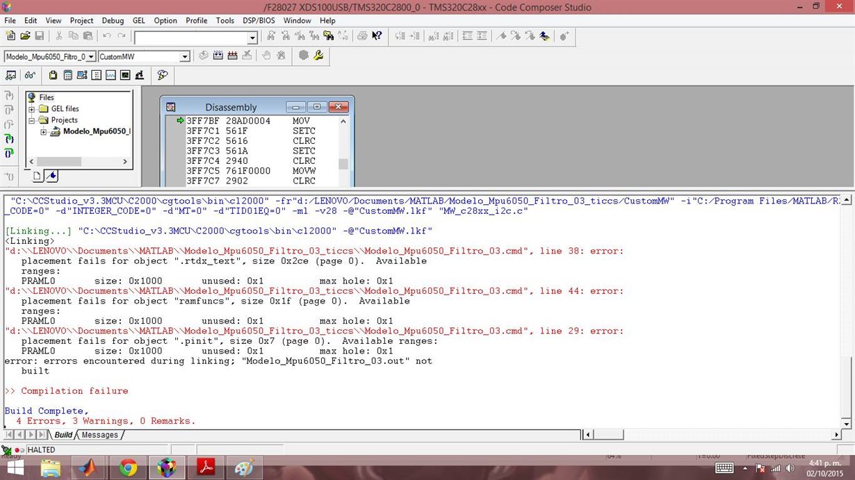
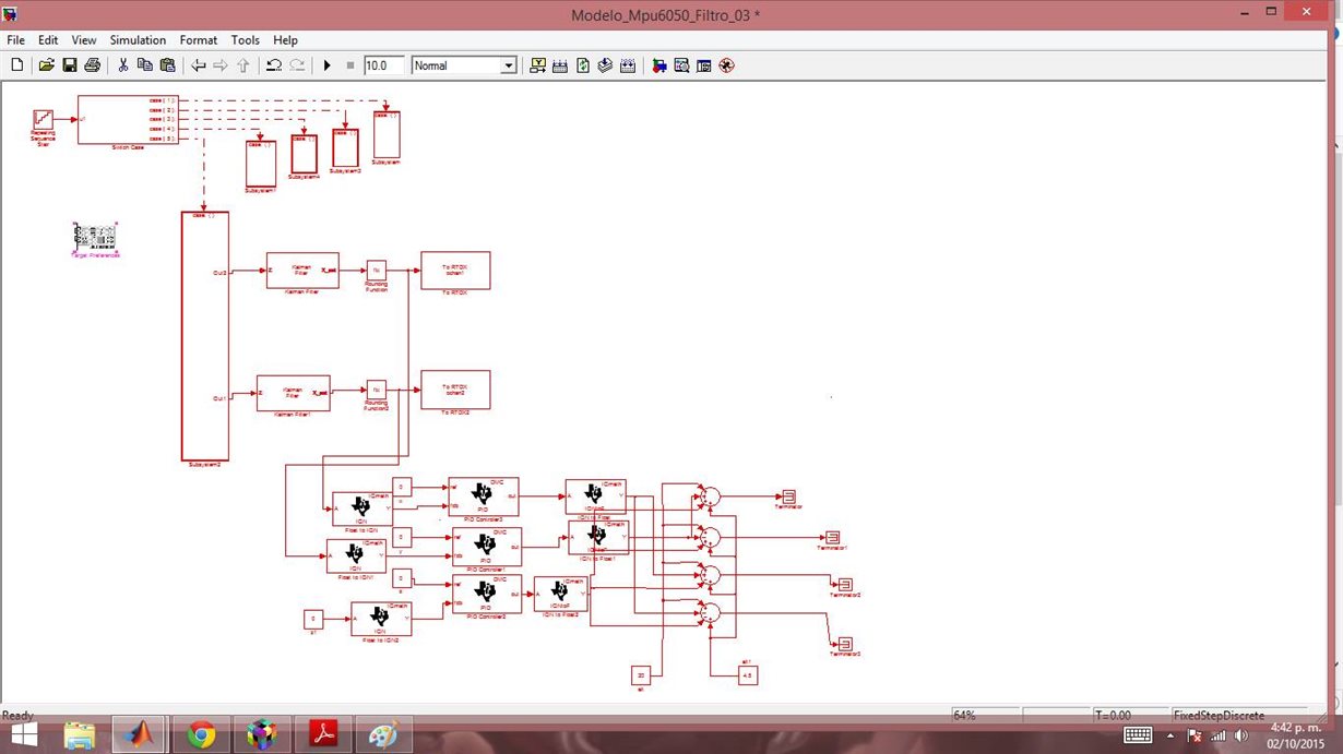
im making a model in matlab/simulink with the library "embedded coder", but sometimes the memory isnt enought... i see that the IQmath.lib and the rtdx.text file are located in the memory PRAML0 but the size of thar files are so big and the memory PRAML0 is only 0x1000


how can i put that files to another more big memory section like FLASH????

or how can i expand that memory???

usually happend when i use rtdx blocks or IQmath operations... i need some help because i need put more things in that proyect.


i try to change the memory section in simulink but, when i build in the ccs appear the next error, maybe i need configurate the changes in the ccs too

the solution should be put that big files in another section of memory, but i dont know how...

if suggest reduce the program remember that i need put more things in that proyect.... at this moment im reading a mpu6050 Gyroscope/accelerometer using i2c communication.

i need make PID control and/or QFT control for a quadcopter... if someone know about that, please write to me.
thanks for the help

  • Hello,

    To change the memory section, open the linker command file (can use a text editor).
    Under the "SECTIONS" part of the linker is where the program and data areas are assigned to a particular memory section.
    If, for example, .pinit needs a larger memory section.
    " .pinit : > PRAML0 PAGE = 0 "
    you can change it to
    " .pinit : > FLASHA PAGE = 0 " to change the memory section it will be placed into.
    You can use this same process to change other program//data areas to different sections.

    Additional linker command file information: processors.wiki.ti.com/.../C28x_Compiler_-_Understanding_Linking

    Best Regards,
    Chris

  • If you can access the CMD file being used to compile the program you can also split some of the sections between different memories by using the ">>" and "|" operators.

    ".ebss :>> PRAML0 | RAMM0M1"
  • Christopher Chiarella and Trey German thank your for the response

    i modified the .cmd and dont appear the error of the image 1, that mean that works, i divide the .text like

    ".text :>> PRAML0 | FLASH, PAGE = 0" (need be continue the memory blocks? or that is good)

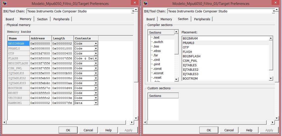
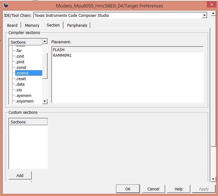
    i can moddified that sections of memory in simulink like i show in the image 3, i just change the .text to FLASH

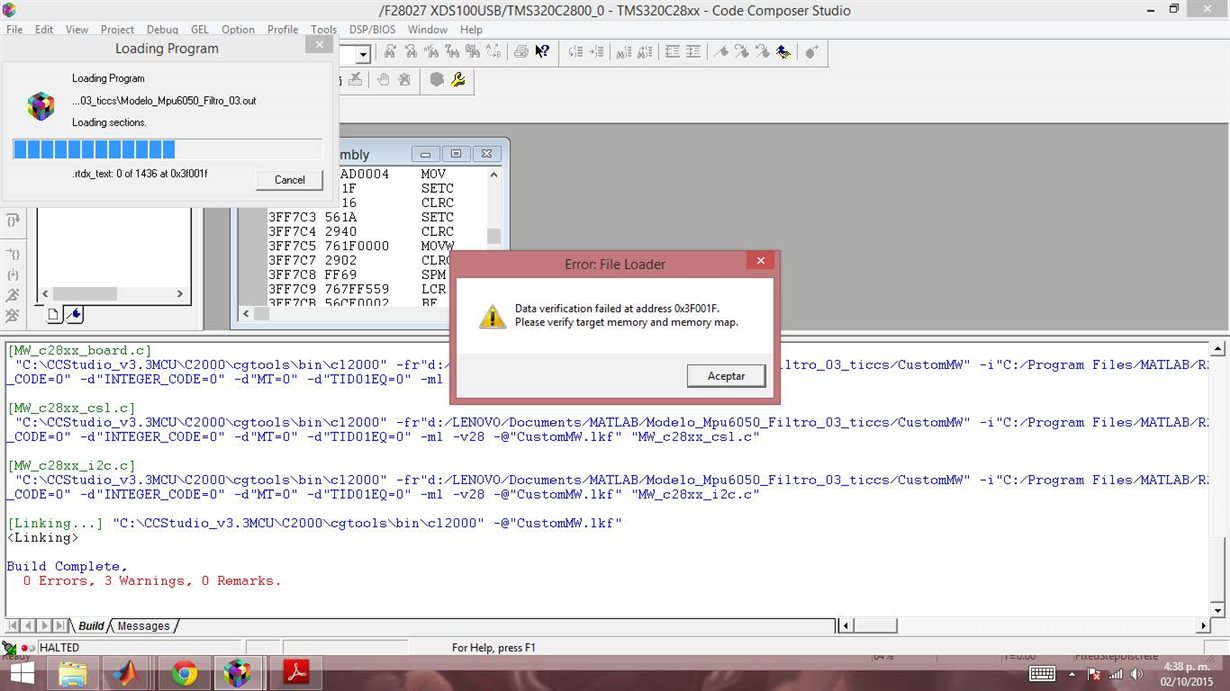
    but when i load the program (.out) appear the error of the image 4

    "Data verification failed at address 0x3xxxxxx
    please verify target memory and target map"

    i need modified another thing in the ccs???
    maybe in simulink?


    edit:


    i find that in the ccs

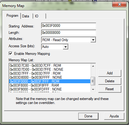
    the 0x003F0000 is the address of the flash memory, say that is ROM to only read

    can i change to RAM??

    or you suggest share the .text with another RAM memory...


    thanks

  • You aren't required to have continuous memory blocks for splitting.
    For Flash, you may need to use the flash programming plugin: e2e.ti.com/.../21513
    Another data verification reason could be a locked device : e2e.ti.com/.../723824

    Additional information for debugging:
    processors.wiki.ti.com/.../Troubleshooting_CCS_-_Data_Verification_Errors
    processors.wiki.ti.com/.../Linker_Command_File_Primer

    Best Regards,
    Chris
  • Thank you for the response... i did that steps to build the program using the "on-chip flash programmer"

    using simulink i change the ".text" file to FLASH, then i build using the "on-chip flash programmer"

    0 errors, 0 warnings

    i fint that steps in mathworks forum

    "

    Some general guidelines to save code in Flash Memory can be found here:

    http://www.mathworks.com/help/ecoder/ug/programming-flash-memory.html

    In order to store generated code in the internal Flash memory of the C28xx DSPs, you need a Flash Programmer (the TI Flash programmer is installed by default with Code Composer Studio). The following process guides you through the necessary steps in detail:

    1. Drag the F2812, F2808, or F28335 Stand alone using Flash Memory Target Preference block into the model. This block can be found in Target Support Package TC2 >> C2000 Target Preferences. If you do not have Target Support Package TC2 installed or you have a different board, use the Custom Board block from Embedded IDE Link CC >> Target Preferences, and manually configure its parameters.

    2. Press "Ctrl + E" to open the Configuration Parameters window. Select Real-Time Workshop >> Embedded IDE Link CC, and set the Build action to "Build". Apply the change and close the window.

    3. Make sure the board is connected to your PC and turned on. Press "Ctrl + B" to build the mode. When this process is completed successfully, MATLAB command prompt displays:

    ### Build complete

    and Code Composer Studio Output window displays:

    Build Complete,

       0 Errors, 0 Warnings, 0 Remarks.

    4. In Code Composer Studio, launch the Flash Programmer by selecting Tools >> F28xx On-Chip Flash Programmer. Select the radio button named "Erase, Program, Verify", and click on the "Execute Operation" button. Once this operation is completed, you should see the following message in the Code Composer Studio Output window:

    Erase/Program/Verify Operation succeeded

    ** End Erase/Program/Verify Operation. *

    5. In Code Composer Studio, Select Debug >> Disconnect. Then, unplug the power for the board, and physically disconnect the board from the PC.

    6. Now that the code is saved in the C28xx DSP chip nonvolatile memory, you must set an indicator for the chip before you can run this code. This indicator is set by the Bootloader Modes of the particular chip. For example, on F2812 eZdsp, you need to change the jumper setting for JP7 from the factory default settings. On F2808 eZdsp, you need to change the switches 1 and 3 on bank SW1 from the factory default settings. On F28335 eZdsp, you need to change the switch 3 on bank SW1 from the factory default settings. For precise instructions, refer to the specific DSP Boot ROM Reference Guide found on the TI Web page:

    http://www.ti.com/

    and the Spectrum Digital ™ Reference Guides for the eZdsp chips:

    http://c2000.spectrumdigital.com/

    7. To run the code in Flash Memory, turn on the board. The code starts to run as soon as the power is plugged in."

    I take that steps in that link

    ok, i have some questions

    - when i burn in the flash using the "on-chip flash programmer" dont let me see the rtdx signals that i saw before when i burn in the ram

    ¿someone can help me? the program build in the target, but i dont know if is running... or stay the serial communication with the PC when i burn in the flash

    -i dont understand the step 6, what exactly i need do in my C28027 about that room bootloader???

    -is possible expand the PRAML0 memmory??? i mean, taking the FLASH memory (ROM) and make to (RAM) using the tool of memmory map in the ccs

    because i need see the datas RTDX in the PC, but i dont know if is possible when i load the program using the "on-chip flash programmer"

    -i read that i only can burn in the flash memmory 1000 times, because that memmory is not like ram memmorys and only recomended burn a few times... its true?


    In conclusion, i need see the rtdx like before, when i burn in the ram, is possible? and what can i do?

    thanks

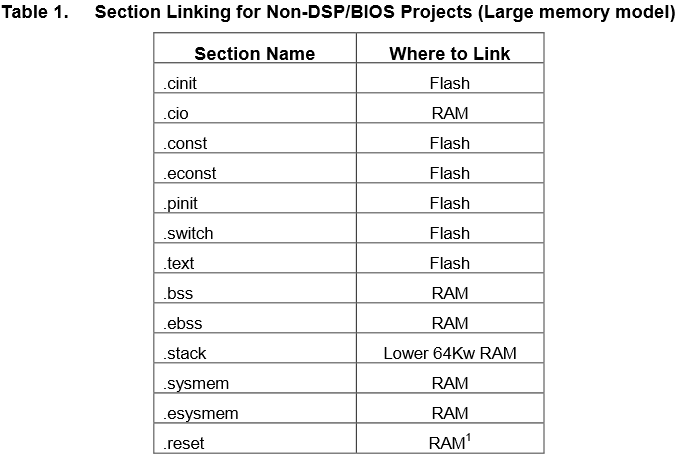
  • I find that document

    in the page 6, the table 1 says


    if my english is right, says that i need put the initialize sections in FLASH

    i will try save that sections like the table 1... and i will coment the results


    Edit: doesnt work, i moddified the sections to FLASH like the table 1... but i cant see the rtdx signals that i saw when i build in the RAM

    someone can help to me???


    thanks