This thread has been locked.

If you have a related question, please click the "Ask a related question" button in the top right corner. The newly created question will be automatically linked to this question.

F28075 Booting from FLASH after DCSM2 Programming

Other Parts Discussed in Thread: CONTROLSUITE

I've been working with the F28075 device and have been running into a strange problem.  I have some execute only code that I've placed in Sector N, allocated it for Zone 2 of the DCSM and secured it.  However after doing this I can no longer boot from FLASH.  

I've tried using the blinky example in controlSUITE.  Before programming Sector N, I can download the blinky example (with FLASH build configuration), power cycle the board and it comes up as expected.  After loading Sector N and securing the DCSM, it will no longer boot after power cycling.  I've tried reprogramming the blinky example as well as erasing the Sector N content.

I've attached the DCSM configuration I've been using.  Any help is appreciated thanks!

DCSM_Z2_ZoneSelectBlock.asm

  • Hi Adam,

    What is the error you are getting? Is device going into reset loop (probe the XRSn pin).

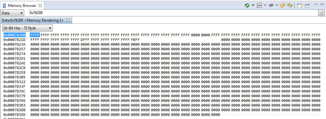
    Also can you dump the Zone2 USER OTP values (0x78200 - 0x783FF) from CCS memory watch window (after unlocking the Zone2) and attach it here.

    Regards,

    Vivek Singh


  • Vivek,

    I don't have an oscilloscope handy right now so I'll check the XRSn pin later.  I'm using the ControlCard and that pin is very hard to get to based on the schematic.  Can you recommend a good location to probe that pin on the ControlCard?

    If I connect to the target after programming blinky into the FLASH it comes up with the PC at 0x3FE2EE, not sure how helpful that is.

    I've attached an image of my Zone 2 USER OTP memory with the password blanked out.

  • Adam,

    Can you check the value in RESC register (Table 2-180. RESC Register Field Descriptions) and  NMISHDFLG (Table 2-63. NMISHDFLG Register Field Descriptions)

    after connecting the target. I hope you have programmed the ECC values as well for Zone2 security settings.

    Regards,

    Vivek Singh

  • Vivek,

    After connecting to the target RESC is 0xC000000B and NMISHDFLG ix 0x0008.

    When I setup my Zone 2 settings I followed the example provided in blinky_with_dcsm. Can you elaborate on what you mean by programming the ECC values?

  • Thanks Adam. I see that "FLUNCERR" bit is set in NMISHDFLG which means there is uncorrectable error from Flash. Look like the ECC for DCSM location is not programmed. ECC programming should be done by flash programming tool. Example code only provides the value for the OTP location and then flash programming tool need to take care of programming ECC values correctly.  Can you check the code for Flash programming tool and see why it's not programming the ECC for DCSM OTP locations?

    Regards,

    Vivek Singh


  • Vivek,

    I'm using CCS to program the flash.  I've included a screenshot of my settings below.  Shouldn't these settings correctly program the ECC?

  • Adam,

    That should program the ECC value properly.  But there is ECC error in your setup which is causing this issue and since you face this issue only after programming the DCSM values (normal Flash code works fine), I am expecting issue is with these values only. Can you check value in UNC_ERR_ADDR_LOW and UNC_ERR_ADDR_HIGH register as well. Please follow following step to check the value in these registers.

    -> Connect the CCS

    -> Issue reset (using CCS).

    -> Hit on RUN button

    After this CPU should halt due to ESTOP instruction and then you can check these register values using CCS memory watch window.

    Also can you confirm that you have installed all the latest CCS updates? You can check this by clicking on "Help -> Check for CCS Updates" in CCS GUI and if it shows any pending patch for C2000 or emulation , please install the same.

    Regards,

    Vivek Singh

  • Vivek,

    If I follow your procedure the processor will run the blinky example code I have programmed in the flash and the values in UNC_ERR_ADDR_LOW & UNC_ERR_ADDR_HIGH are 0.

    If I don't issue a reset after connecting to the target, I get a value of 0x78210 for UNC_ERR_ADDR_LOW.

    I am now on the very latest ccs, when I did the programming I was on version 4.1.4.3 of TI C2000 Device Support and 6.0.14.0 of TI Emulators with everything else at the latest.
  • Ok, CCS gel file must be disbaling the Flash ECC hence it works with emulator connected. But in other case you got the address correct. It's giving ECC error for Ist value programmed in DCSM OTP which is PSWDLOCK.

    Can you check the value @address 0x1071042.

    Regards,

    Vivek Singh

  • After connecting but not resetting the target the value is: 0xFFFFFFFF
  • Hi  Adam,

    This mean ECC is not programmed. Could you re-try programming the PSWDLOCK location (0x78210) in DCSM OTP (same value as before) and check if this changes the value @address 0x107142. If yes then you need to re-program all other values in DCSM OTP (with same value) and try this.

    Regards,

    Vivek Singh 

  • Vivek,

    I reprogrammed all of DCSM OTP & Sector N using my generated image and the value at 0x1071042 is still 0xFFFFFFFF. I checked before and after a power cycle. I made sure that Auto ECC Generation was checked.

    Is the address I should be checking 0x1071042 or 0x107142?
  • Adam,

    Address is correct (0x1071042). In fact I am assuming that all the location from address 0x1071000-0x107107F will be 0xFFFFFFFF in your case because ECC values are not getting programmed.  Right?

    Also while programming, you are not getting any error from CCS. Right?

    I don't see any reason why ECC not getting programmed. You may want to re-install the CCS and then try again programming these values.

    Regards,

    Vivek Singh


  • Vivek,

    It doesn't seem like the CCS flashing algorithm is setting any of the ECC values.  I grabbed a screenshot below.

    I'm not getting any errors in the Console after completing this operation.  Nor did I see any pop-up errors.

    I'll try reinstalling CCS, can you test this procedure on your hardware to see if you observe the same behavior?

  • Ok, I see here that ECC values for other settings are getting programmed properly (after address 0x1071044). So it's strange that only for PSWDLOCK the ECC value is not getting programmed.  I'll check this on my setup. Till then you don't need to re-install the CCS. 

    Can you also try using the CCS flash plug-in GUI to program PSWDLOCK value. In GUI you'll find a PSWDLOCK field for Zone2. You can provide value 00000000 for PSWDLOCK and FFFFFFFF for CRCLOCK and the click on "Program OTPSECLOCK" to just program these value. After that you can check the ECC value to see if it's getting programmed.

    Regards,

    Vivek Singh

  • Here is the snapshot for the CCS Flash plug-in GUI -


    Regards,

    Vivek Singh

  • Vivek,

    Programming via the CCS Flash Plug-in will write to the ECC values.  

    So why don't the ECC values get programmed by loading the outfile from CCS?  Isn't is effectively the same flashing algorithm?

  • Adam,

    That's good. Now you should be able to run the example code in standalone mode.

    It should get programmed by loading the outfile but look like there is some exception for this field (ECC for other fields are getting programmed via outfile). Both (GUI and outfile load) use same API but there is some difference.

    I'll check this on my setup.

    Let me know if you face any further issue in running your test.

    Regards,

    Vivek Singh

  • Vivek,

    It is important that this issue gets resolved from loading the outfile only and not manually setting the password and crc lock bits. The test I was running is to figure out what is going wrong. I need to be able to load an outfile via CCS and have it correctly set the ECC bits.
  • Hi Adam,

    I tried this on my setup and I see ECC getting programmed correctly for PSWDLOCK field in DCSM OTP. Can you try this on another fresh part and if there also it does not work then you should try re-installing the CCS and try again.

    Also if there is no issue with sharing your .out file, please send me the same to try on my setup (to see if there is something with .out).

    Regards,

    Vivek Singh

  • Vivek,

    How did you program the PSWDLOCK?  Did you do it via the Flash Plug-in or via an out file?  I agree that the Flash Plug-in seems to work, but setting that via an out file doesn't work.

    I got a fresh part and imported blinky_with_DCSM from controlSUITE into CCS.  I updated the DCSM_Z2_ZoneSelectBlock.asm and 2807x_dcsm_lnk_cpu1.cmd to match the attached files.  I switched the build configuration into FLASH.  Built and download the project.  CCS did not write the ECC values for the PSWDLOCK register.  This part has the same behavior as the previous part and I only loaded in TI example code.

    DCSM_Z2_ZoneSelectBlock.asm.txt
    ;// TI File $Revision: /main/2 $
    ;// Checkin $Date: December 7, 2011   18:25:12 $
    ;//###########################################################################
    ;//
    ;// FILE:	DCSM_Z2_ZoneSelectBlock._asm
    ;//
    ;// TITLE:	F2837x Dual Code Security Module Zone 2 Zone Select Block Values.
    ;// 
    ;// DESCRIPTION:
    ;//
    ;//         This file is used to specify Z2 DCSM OTP and zone select
    ;//         values to program into the Zone 2 zone select locations in OTP
    ;//         Value depends on Linkpointer).
    ;//
    ;//         In addition, the 60 reserved values after the zone select block 
    ;//         are all programmed to 0x0000 as well.
    ;//
    ;//###########################################################################
    ;//
    ;// Original source based on D.A.
    ;// 
    ;// $TI Release: F2837xD Support Library v110 $
    ;// $Release Date: Mon Apr  7 10:35:37 CDT 2014 $
    ;//###########################################################################
    
    
    ; !!IMPORTANT!!: The "dcsm_otp_z2" section contains the Z2 LINKPOINTER which 
    ; determines the location of the Z2 Zone Select block.  If the LINKPOINTER 
    ; is changed, then the "dcsm_zsel_z2" section in the *_dcsm_lnk_cpu1.cmd command linker 
    ; file must also change to an address decoded from the value specified 
    ; in the Z2-LINKPOINTER location. 
    
    ; The "dcsm_zsel_z2" section contains the actual Z2 Zone Select Block values 
    ; that will be linked and programmed into to the DCSM Z2 OTP Zone Select block
    ; in OTP.  
    ; These values must be known in order to unlock the CSM module. 
    ; All 0xFFFFFFFF's (erased) is the default value for the password locations (PWL).
    
    ; It is recommended that all values be left as 0xFFFFFFFF during code
    ; development.  Values of 0xFFFFFFFF do not activate code security and dummy 
    ; reads of the Z2 DCSM PWL registers is all that is required to unlock the CSM.  
    ; When code development is complete, modify values to activate the
    ; code security module.
    
          .sect dcsm_otp_z2
    	  
    	  .long 0xFFFFFFFF     ;Z2-LINKPOINTER1
    	  .long 0xFFFFFFFF     ;Reserved
    	  .long 0xFFFFFFFF     ;Z2-LINKPOINTER2
    	  .long 0xFFFFFFFF     ;Reserved
    	  .long 0xFFFFFFFF     ;Z2-LINKPOINTER3
    	  .long 0xFFFFFFFF     ;Reserved
    	  .long 0xFFFFFFFF     ;Reserved
    	  .long 0xFFFFFFFF     ;Reserved
    	  .long 0x00000000     ;Z2-PSWDLOCK (do not allow PSWD access)
    	  .long 0xFFFFFFFF     ;Reserved
    	  .long 0xFFFFFFFF     ;Z2-CRCLOCK (do allow CRC access)
    	  .long 0xFFFFFFFF     ;Reserved
    	  .long 0xFFFFFFFF     ;Z2-JTAGLOCK (do not allow JTAG access)
    	  .long 0xFFFFFFFF     ;Reserved
    	  .long 0xFFFFFFFF     ;Reserved
    	  .long 0xFFFFFFFF     ;Z2-BOOTCTRL
    
          .sect dcsm_zsel_z2
    
          .long	0xFFFFFFFF		;Z2-EXEONLYRAM
          .long	0xFFFFDFFF		;Z2-EXEONLYSECT (Flash Sect B is exe only)
          .long	0xFFFFFFFF		;Z2-GRABRAM
          .long	0xFBFFFFFF		;Z2-GRABSECT (Flash Sect B is Secure to Zone 2)
    	  
    	  ; password generated from http://randomkeygen.com/ 128-bit WEP keys
    	  ; scrubbed to NEW random password
          .long	0x895F8992		;Z2-CSMPSWD0 (LSW of 128-bit password)
          .long	0x16B8CCDD		;Z2-CSMPSWD1
          .long	0xD59C3BC9		;Z2-CSMPSWD2
          .long	0x4593D492		;Z2-CSMPSWD3 (MSW of 128-bit password)
    	  
    ;----------------------------------------------------------------------
    
    ; For code security operation,after development has completed, prior to
    ; production, all other zone select block locations should be programmed
    ; to 0x0000 for maximum security.        
    ; If the first zone select block at offset 0x20 is used, the section
    ;"dcsm_rsvd_z2" can be used to program these locations to 0x0000.
    ; This code is commented out for development.
    
            .sect dcsm_rsvd_z2
            .loop (1e0h)
                  .int 0x0000
            .endloop
    
    ;//===========================================================================
    ;// End of file.
    ;//===========================================================================


    2807x_dcsm_lnk_cpu1.cmd.txt
    /* this linker command file is to be included if user wants to use the DCSM feature on the device
     * DCSM  means Dual Zone Code Security Module.
     * This linker command file works as an addendum ot the already existing Flash/RAM linker command file
     * that the project has.
     * The sections in the *_ZoneSelectBlock.asm source file is linked as per the commands given in the file
     * NOTE - please note fill=0xFFFF, this helps if users include this file in the project by mistake and 
     * doesn't provide the needed proper *_ZoneSelectBlock.asm sources . 
     * Please refer to the Blinky DCSM example in the controlsuite examples for proper usage of this.
     * 
     * Once users are confident that they want to program the passwords in OTP, the sDSECT section type can be removed.
     * 
    */ 
    
    MEMORY
    {
    PAGE 0 :  /* Program Memory */
     
       /* Part of Z1 OTP.  LinkPointers/PSWD LOCK/CRC LOCK/JTAG lock/ Boot Ctrl */
       DCSM_OTP_Z1_P0	: origin = 0x78000, length = 0x000020		
       /* Part of Z2 OTP.  LinkPointers/PSWD LOCK/CRC LOCK/JTAG lock/ Boot Ctrl */
       DCSM_OTP_Z2_P0	: origin = 0x78200, length = 0x000020		
       
       /* DCSM Z1 Zone Select Contents (!!Movable!!) */
       /* Part of Z1 OTP.  Z1 password locations / Flash and RAM partitioning */
       DCSM_ZSEL_Z1_P0	: origin = 0x78020, length = 0x000010	
       
       /* DCSM Z1 Zone Select Contents (!!Movable!!) */
       /* Part of Z2 OTP.  Z2 password locations / Flash and RAM partitioning  */
       DCSM_ZSEL_Z2_P0	: origin = 0x78220, length = 0x000010
       DCSM_ZSEL_RSVD_Z2_P0 : origin = 0x78230, length = 0x0001e0
    }
    
    
    SECTIONS
    {
       dcsm_otp_z1		: > DCSM_OTP_Z1_P0		PAGE = 0, type = DSECT
       dcsm_otp_z2		: > DCSM_OTP_Z2_P0		PAGE = 0
       
       dcsm_zsel_z1		: > DCSM_ZSEL_Z1_P0		PAGE = 0, type = DSECT
       dcsm_zsel_z2		: > DCSM_ZSEL_Z2_P0		PAGE = 0
       dcsm_rsvd_z2    : > DCSM_ZSEL_RSVD_Z2_P0 PAGE = 0
    		 
    }
    
    /*
    //===========================================================================
    // End of file.
    //===========================================================================
    */
    

  • Hi Adam,

    I programmed it using the .out file. Strange that it's not working for you.

    Can you send me a sample .out file which has this issue and I can try the same on my setup.

    Also did you re-install the CCS and tried the same?

    Regards,

    Vivek Singh

  • Vivek,

    I've attached the out file that I used for my test.  

    blinky_with_dcsm_cpu01.out.txt

    One thing I did observe is that if I did this test on a card where I have used the Flash plug-in to program the PSWDLOCK & CRCLOCK so that the correct value is programmed to 0x1071042, than it will succeed on each subsequent programming.  But if I do this on a completely blank card it will not not write the value to 0x1071042.

    Can you describe your test setup in addition detail so that we can be sure you are testing the same way I did?  Did you use a completely blank card?  Did you modify the default linker file so that your outfile contains DCSM Z2 content?

  • Hi Adam,

    One thing I did observe is that if I did this test on a card where I have used the Flash plug-in to program the PSWDLOCK & CRCLOCK so that the correct value is programmed to 0x1071042, than it will succeed on each subsequent programming.  But if I do this on a completely blank card it will not not write the value to 0x1071042.

    This is part of OTP (One Time Programmable) so once you program the value using the Flash plug-in, it remain unchanged forever. It doesn't get erase during subsequent programming and programmer doesn't give error because value is same. So it may look like that it's getting re-programmed during subsequent programming operation but it's not.

    Can you describe your test setup in addition detail so that we can be sure you are testing the same way I did?  Did you use a completely blank card?  Did you modify the default linker file so that your outfile contains DCSM Z2 content?

    I don't have any special setup for this and I have used completely blanked (fresh) device. Also appropriate changes were made in linker cmd file so that outfile has all the values for OTP to be programmed. 

    I am yet to try the .out file you have sent. I'll update you on that tomorrow.

    Regards,

    Vivek Singh 

  • Vivek,

    Thanks for continuing to look into this.  I tried reinstalling CCS, but that did not resolve the issue.

  • Adam,

    I tried the .out you sent and yes, I could see that with this .out, the ECC location for PSWDLOCK address is not getting programmed but when I use the .out I have, it gets programmed correctly. It's very strange. We are looking into this.

    Meanwhile, could you remove the following code from the asm file and re-try programming the part.

            .sect dcsm_rsvd_z2
            .loop (1e0h)
                  .int 0x0000
            .endloop

    Regards,

    Vivek Singh

  • Vivek,

    I'm glad to hear I'm not going completely crazy :)

    I removed the requested code from the asm file but it still didn't program the ECC location for PSWDLOCK. I did not modify the linker file, so it still has the lines:

    DCSM_ZSEL_RSVD_Z2_P0 : origin = 0x78230, length = 0x0001e0
    dcsm_rsvd_z2 : > DCSM_ZSEL_RSVD_Z2_P0 PAGE = 0

    But in the map, it isn't assigning anything to that memory location.
  • Could you attach the CCS project file for this one.Regards,Vivek Singh
  • Here is the CCS project.

    blinky_with_DCSM.7z

    I also modified the linker.  It is attached below.

    7120.2807x_dcsm_lnk_cpu1.cmd.txt
    /* this linker command file is to be included if user wants to use the DCSM feature on the device
     * DCSM  means Dual Zone Code Security Module.
     * This linker command file works as an addendum ot the already existing Flash/RAM linker command file
     * that the project has.
     * The sections in the *_ZoneSelectBlock.asm source file is linked as per the commands given in the file
     * NOTE - please note fill=0xFFFF, this helps if users include this file in the project by mistake and 
     * doesn't provide the needed proper *_ZoneSelectBlock.asm sources . 
     * Please refer to the Blinky DCSM example in the controlsuite examples for proper usage of this.
     * 
     * Once users are confident that they want to program the passwords in OTP, the sDSECT section type can be removed.
     * 
    */ 
    
    MEMORY
    {
    PAGE 0 :  /* Program Memory */
     
       /* Part of Z1 OTP.  LinkPointers/PSWD LOCK/CRC LOCK/JTAG lock/ Boot Ctrl */
       DCSM_OTP_Z1_P0	: origin = 0x78000, length = 0x000020		
       /* Part of Z2 OTP.  LinkPointers/PSWD LOCK/CRC LOCK/JTAG lock/ Boot Ctrl */
       DCSM_OTP_Z2_P0	: origin = 0x78200, length = 0x000020		
       
       /* DCSM Z1 Zone Select Contents (!!Movable!!) */
       /* Part of Z1 OTP.  Z1 password locations / Flash and RAM partitioning */
       DCSM_ZSEL_Z1_P0	: origin = 0x78020, length = 0x000010	
       
       /* DCSM Z1 Zone Select Contents (!!Movable!!) */
       /* Part of Z2 OTP.  Z2 password locations / Flash and RAM partitioning  */
       DCSM_ZSEL_Z2_P0	: origin = 0x78220, length = 0x000010
       DCSM_ZSEL_RSVD_Z2_P0 : origin = 0x78230, length = 0x0001e0
    }
    
    
    SECTIONS
    {
       dcsm_otp_z1		: > DCSM_OTP_Z1_P0		PAGE = 0, type = DSECT
       dcsm_otp_z2		: > DCSM_OTP_Z2_P0		PAGE = 0
       
       dcsm_zsel_z1		: > DCSM_ZSEL_Z1_P0		PAGE = 0, type = DSECT
       dcsm_zsel_z2		: > DCSM_ZSEL_Z2_P0		PAGE = 0
       dcsm_rsvd_z2    : > DCSM_ZSEL_RSVD_Z2_P0 PAGE = 0
    		 
    }
    
    /*
    //===========================================================================
    // End of file.
    //===========================================================================
    */
    

    I'm using v160 in ControlSUITE.

  • Adam,

    The linker file you have sent only has section for OTP locations and those are also defined as "type = DSECT" which means these sections will be be loaded. Please send the cmd file which you used to create the .out file which you have sent earlier.

    [Update]

    Nevermind. I see you have removed the DSECT for Zone2 section.


    Regards,

    Vivek Singh

  • Vivek,

    I was using ControlSUITE v160 F28075 support files.  I didn't want to go through ControlSUITE and copy out all of the files that the project includes.  If you place my project at: C:\ti\controlSUITE\device_support\F2807x\v160\F2807x_examples_Cpu1 all of the links will work correctly.

  • Hi Adam,

    After further debug we were able to find the issue. LINKPOINTER locations in OTP don't have ECC (because user need to re-program it) hence the plug-in tool doesn't not program ECC for the LINKPOINTER locations. Flash plug-in takes the block of data based on the section defined in linker cmd file and programs it in flash. And while passing the block is start address is of LINKPOINTER then it does not programs the ECC. In this case since all the security settings except of zone_select_block were defined in one section and start of the section was address for LINKPOINTER hence it did not program the ECC for this full block but for zone_select_block it programmed the ECC correctly. To solve this issue, we need to define different section for LINKPOINTERs in cmd file and place the link pointers in that section. The test setup I was using had different section for LINKPOINTERs hence it worked ok for my testcase.

    I have modified the testcase cmd file and "DCSM_Z2_ZoneSelectBlock.asm" file accordingly (project attached) and that fixed the issue.  We'll fix the example code in controlSUITE as well.

    Thank you for your patience.

    Regards,

    Vivek Singhblinky_with_dcsm_modified.zip

  • Vivek,

    I modified my ROM image generation based on the recommendations you provided and I was able to verify that the ECC bits are now being correctly written by my self-locking out file.

    Additionally I can boot from FLASH using the controlSUITE provided blinky example.

    Thanks for all of your help.