This thread has been locked.

If you have a related question, please click the "Ask a related question" button in the top right corner. The newly created question will be automatically linked to this question.

Use all EPWMs on TI Launchpad F28377s

From the datasheet it looks like only EPWM1 ... EPWM8 are routed from the DSP to the pins, while some others (EPWM9 and EPWM10 for instance) are used with a low pass filter in order to work as a DAC.

Is there a way to use all EPWM modules (specifically EPWM9 ... EPWM12) of a TI Launchpad delfino F28377S?

Thank you very much for your help!

  • Stefano,

    Perhaps you can depopulate R36, R37, R40, and R41 from the Launchpad, and tap the ePWM signals at the resistor pads.

    Regards,

    David

  • David,

    Thank you for your reply. I could indeed short R and unsolder C, that would theoretically be correct althoug kind of a hack.

    What concerns me is that in the PWM mux configuration (Mux = 1) it is the EQEP1A channel for GPIO20 instead of DAC1 selected. And I am a bit lost with what is inputs and what is outputs on this board ... Cannot i select the mux for each single signal?
  • Stefano,

    Each pin has multiple possible functions. You can set the mux bits as you want for each pin. For GPIO20, mux configuration #1 is EQEP1A function. Mux configuration #5 gives you EPWM11A. In general, a particular pin could be an input or an output, depending on which function you select for it.

    See the F28377S datasheet SPRS881B, Table 4-4 for the complete pin mux listings.

    Regards,
    David
  • David,

    Thank you for your answer. I though the Launchpad expressively limited the number of mux to 0,1,2,3. So you're basically saying that the Launchpad is not a limited version of the TMS320F2837xS and that it's just that the Launchpad datasheet is not complete?

    Regards,
    Stefano.
  • Stefano,

    The Launchpad has regular F28377S silicon on it. Where are you seeing that the Launchpad limits the mux configurations to 0,1,2,3 options?

    - David
  • David,

    From the datasheet of the Launchpad: www.ti.com/.../sprui25a.pdf (Table 1,2,3,4 of pages 8-9).

    Anyway you replied my question perfectly. I'm looking forward to experiment with the launchpad capabilities ;).

    Have a nice day!
    Stefano
  • HI,

    where do you see that all PWMs can be routed to pins?

    From what I can tell there is a typo and GPIO2,3 are EPWM2A,B, so EPWM1 is not routed to pins.

    So you've got EPWM2,6 and 10 on J8 and you've got EPWM 7,8,9 and 11 on J4

    And EPWM 11 and 10 are routed twice. Once directly and once through RC circuits David has mentioned

    All in all you can get 7 complementary pairs, which is great, but could be better as there are couple of empty pins left.

    And routing could be better as a lot of existing code uses EPWM1,2,3
  • stefano65 said:

     
    From the datasheet of the Launchpad: www.ti.com/.../sprui25a.pdf (Table 1,2,3,4 of pages 8-9).

    Yes, those tables list only mux options 0,1,2,3.  But it also says in the text of section 6.1 "Table 1 through Table 4 lists the pin out and pin mux options for the C2000 LaunchPad. Additional muxing options are available and can be found in the TMS320F2837xS Delfino Microcontrollers Data Manual (SPRS881)."  So there you have it.  The tables are not showing all options, and that is stated.

    Regards,

    David

  • Mitja,

    Mitja Nemec said:
    HI,

    where do you see that all PWMs can be routed to pins?

    From what I can tell there is a typo and GPIO2,3 are EPWM2A,B, so EPWM1 is not routed to pins.

    So you've got EPWM2,6 and 10 on J8 and you've got EPWM 7,8,9 and 11 on J4

    And EPWM 11 and 10 are routed twice. Once directly and once through RC circuits David has mentioned

    All in all you can get 7 complementary pairs, which is great, but could be better as there are couple of empty pins left.

    And routing could be better as a lot of existing code uses EPWM1,2,3

    You're right about the typo in sprui25a, Table 4.
    GPIO2 is EPWM2A and GPIO3 is EPWM2B.  I'll notify the C2000 team to get this fixed.
    I went through all the pins available on the Launchpad headers.  Here is what you can get for ePWM:
    GPIO2 - ePWM2A
    GPIO3 - ePWM2B
    GPIO4 - ePWM3A
    GPIO10 - ePWM6A
    GPIO11 - ePWM6B
    GPIO12 - ePWM7A
    GPIO13 - ePWM7B
    GPIO14 - ePWM8A
    GPIO15 - ePWM8B
    GPIO16 - ePWM9A
    GPIO17 - ePWM9B
    GPIO18 - ePWM10A
    GPIO19 - ePWM10B
    GPIO20 - ePWM11A
    GPIO21 - ePWM11B
    To get the other ePWM signals, I guess you would have to do some wire soldering at the package.
    Regards,
    David
  • Actually, I realized just now that the Launchpad has the PZ 100-pin QFP package of the F28377S on it.  This package does NOT have all the signals available.  For example, GPIO0 and GPIO1 are not available (meaning, ePWM1A and ePWM1B are not available).  So, soldering wires, as I suggested earlier, won't help.

    The reason this package was used was cost.  This is the lowest cost package.  The Launchpad is a low cost development board.  They go together.

    Regards,

    David

  • David,

    Thank you for this answer. As I was still trying to work with the datasheet I couldn't understand how come EPwm2 was routed to EPwm1 pins ...

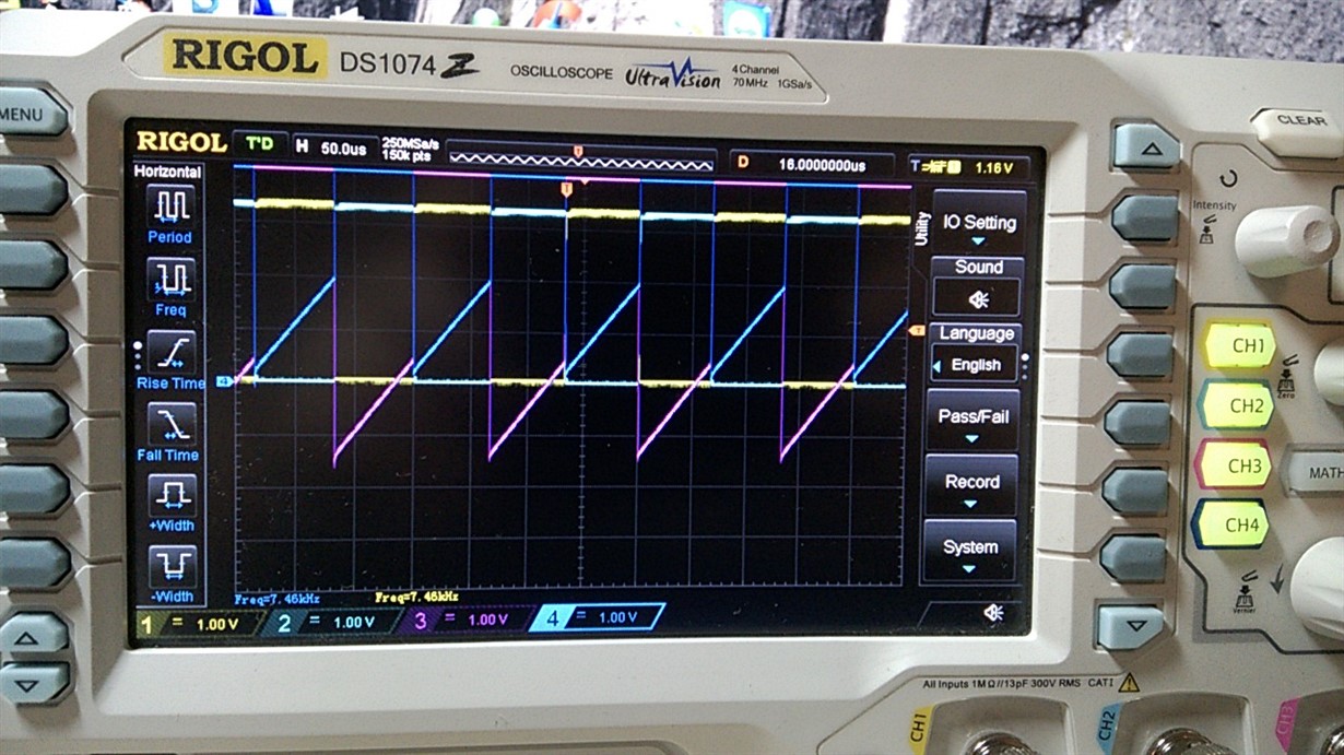
    However I can only work with EPWM2 for now. EPWM1 is not routed as stated by you and EPWM3(A) is a DAC I guess or some kind of strange signal (partially sawtooth where the PWM is low, square where PWM is high). I guess some kind of filtering or high impedance state instead if being pulled low.
  • A screenshot of what I previously mentioned (problem: the triangular / sawtooth shape instead of square)

    Furthermore the PWM frequency seems to vary according to the CMPA value which is very weird