This thread has been locked.

If you have a related question, please click the "Ask a related question" button in the top right corner. The newly created question will be automatically linked to this question.

SCI boot for TMS320F2837xD controlCARD

Other Parts Discussed in Thread: CONTROLSUITE, TMS320F28335, C2000WARE

The TMS320F2837xD controlCARD uses GPIO28 & 29  as SCI pins. However, in Boot-from-SCI mode, the DSP will use GPIO84 & 85 as default pins. The information guide give three options to solve this problem.

Option 1:  Change the boot mode to Get Mode and then, in your main flashed code, you can decide to call the bootloader for SCIBoot IOOption2 (in the bootROM) always or based on whatever is desired.

Option 2: Change the boot mode to Get Mode and configure the OTP such that SCIBoot IOOption2 is called. This is really only an option if you always want to boot from SCI or Parallel GPIO because you’ll be overwriting your ability to boot from Flash.

Option 3:  With an emulator connected (TRSTn = 1), registers can be set such that SCIBoot’s IOOption2 boot mode is called.

Here are the questions:

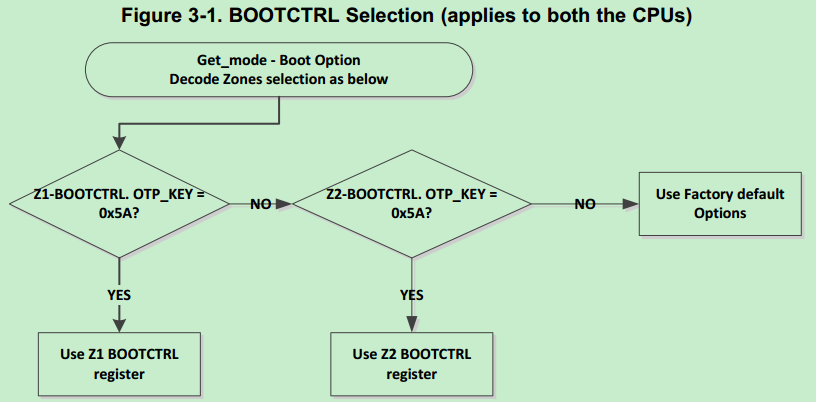
1. For option 1, how does the user to call the bootlader for SCIBoot IO option2 in the main flash code? In Get Mode, the Zx-OPTBOOTCTRL will be used to decide the boot procedure as shown below.


As the Zx-BOOTCTRL register is OTP, the boot procedure will be fixed permanently. So, how to implement "base on whatever is desired"?

2. Does the registers in option 3 refer to EMU_BOOTCTRL? EMU_BOOTCTRL is 32 bits from 0xD00, which is the start address of PieVectTable. So how to set this register?

  • Hi vesgine,

    1. What is meant is that you can set the GPIO boot pins such that the device will use Get Mode.  Next, don't do anything to the OTP.  As a result, the device will boot to FLASH.  At the beginning of the flash code (perhaps in main), you can determine what boot mode you want and under what conditions.  Your code in flash will then call one of the boot ROM functions that exists in ROM.  You can do this by potentially jumping to a specific address.  The Boot ROM source can be found at the below:
    \controlSUITE\libs\utilities\boot_rom\

    2. Yes, EMU_BMODE = 0x81.  I understand your question, but am not aware of the answer.   I will ask another member of my team to respond.  Note that we only recommend this option for validation.  In an end application, we don't want TRSTn to be high during operation when an emulator is not connected.


    Thank you,
    Brett

  • yes for #2, the EMU_BMODE is supposed to be set up either via GEL script or from Memory window. It is for debug only.

    and I agree with what Brett suggested for #1.

    Hope this helps

    Best Regards
    Santosh Athuru

  • Hi, Brett

    Is there any specifications about how to use the boot ROM functions? Or is there any sample codes(project) about utilizing these functions? How to add these functions into my project?

    Best Regards,
    vesgine
  • Hi, Brett

    There is another question.
    If I just want to use GPIO84 & 85 as SCI pins in Boot-from-SCI mode, then GPIO72 must be forced low and GPIO84 must be forced high on power-up. In this case, will the GPIO84 still work correctly as SCI pin after power-up?

    Best regards,
    vesgine
  • Hi vesgine,

    1. I think it's best to ask what you want to do when you boot from SCI.  Are you wanting to program the flash or use the SCI bootloader directly (so that it could be used with something like C2Prog)?
      https://e2e.ti.com/support/microcontrollers/c2000/f/171/p/514556/1872465

      If the bootloader code is sufficient for you (just with GPIO28 & GPIO29), you may be able to jump to the bootloader address.  Or it may be easier to pull the relevant bootloader code that you wish to use into your project.

    2. Yes, as long as the C2000 is the only thing able to drive the pin, you should be fine.
      https://e2e.ti.com/support/microcontrollers/c2000/f/171/p/518367/1887010

    Thank you,
    Brett

  • Hi Brett,

    What I want is to use the SCI bootloader and program the flash using C2Prog. I have read all the discussions you suggested thoroughly.
    And yes, it works well. Verification on TMS320F28335 is successful. Thanks very much!
    I will verify it on TMS320F2837xD later. Is there any specific caution that I need to take care of? Because there are two CPUs on TMS320F2837xD.

    Best regards,
    vesgine
  • C2Prog supports programming TMS320F2837xD. C2Prog manual walks you through on how to program flash in both the cores.
  • Hi, Brett

    SCI boot from application for 28335 was verified before. Now I try to implement it on 28379D, but it failed.

    The platform is F2837x controlCARD R1.3 with F28379D on it. The main code is shown as below.

    Because the default SCI boot option use GPIO84 and GPIO85 and the controlCARD use GPIO28 and GPIO29 as SCI-A pins, the parameter 0xF0 is used here when calling SCI_Boot function.

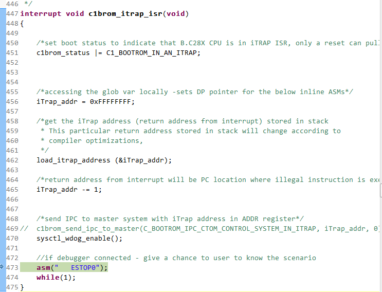
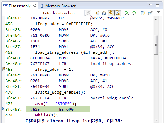
    Firstly, I run the code above and enable a breakpoint at line 27. Then I start C2Prog and try to program the FLASH. However, the program doesn’t stop at the breakpoint but entry a error place shown below(Line 473).

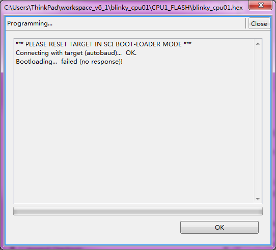
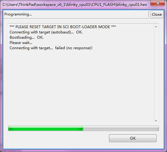
    The C2Prog give the message below.

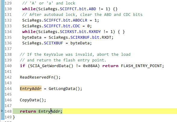
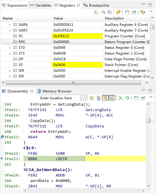
    Then I step into the SCI_Boot function again. The program can run to the end of this function(line148) with EntryAddr equals to 0 as shown below.

    It seems that the SCI_Boot function works well. But the error occurred when the program branched to point 0x0 and started from there. So what’s the problem?

    Besides, there are two version of boot rom for F2837x in the folder of C:\ti\controlSUITE\libs\utilities\boot_rom, namely F2837x_rev0 and F2837x_revb. What’s the differences between them?

  • Vesgine

    What causes an iTrap: processors.wiki.ti.com/.../Interrupt_FAQ_for_C2000

    Verify that everything was programmed in memory correctly and an illegal opcode isn't causing your iTrap.
    For F28379D, use the latest F2837x_revb boot ROM source.

    Best Regards
    Chris
  • Hi, Chris

    I couldn't insert a return instruction nor a breakpoint into the c1brom_itrap_isr. When the program stopped at "asm("ESTOP0")", the variable iTrap_addr equals to 0. At this time, the stack memory and disassembly info are shown below.

    The project(blinky_cpu01) I used is come from controlSUIT except adding sci booting codes as I posted before. How to verify that everything was programmed in memory correctly and an illegal opcode? Is it poosible to do the same experiment to see how this happens? Because all the hardware and software are provided by TI and C2Prog(v1.7f-b5823) which are standard products. The CCS version is 6.1.1.00022 and compiler version is v6.4.9

  • Hi Vesgine,

    On following point,

    I couldn't insert a return instruction nor a breakpoint into the c1brom_itrap_isr.

    This function is ROM function which is inside ROM (read only memory) so you can not insert any instruction here. For breakpoint, you need to use hardware breakpoint instead of software breakpoint. Please note that there are only two hardware breakpoints allowed so if you have already used them, you'll not be able to use further breakpoints. You need to remove other breakpoints to enable this one.

    Regarding ITRAP, please check the value at address location 0x0 in CCS memory watch window (like you checked the stack value). Look like 0x0 address does not have proper code hence CPU is getting ITRAP.

    Regards,

    Vivek Singh

  • Hi, Vivek

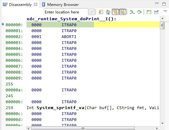
    The value at address location 0x0 is shown below.

    I stepped into the function SCI_Boot() and found that the address 0x0 is returned by SCI_Boot() as shown below.

    The LRETR instruction returns PRC register which is 0. Then the program jumps to address 0x0 and ITRAP occures.

  • Now I found out the reason of ITRAP. The CopyData() function of SCI_Boot is used to copy data from the C2Prog during bootloading. I stepped into this function and found that the DestAddr of the first block is 0x400 which is the start address of stack memory assigned by cmd unfortunately. This cause the stack memory is overwritten by C2Prog which leads to CPU getting ITRAP. So I changed the start address of stack memory from 0x400 to 0xB800. The bootloading is OK now. But the flash programming still failed with the info shown below.

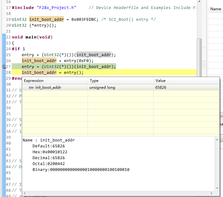
    I also stepped into the program and found that the SCI_Boot() function executed correctly with the return value equaled to 0x10122. The program then jumped to 0x10122 and never returned.

  • Hi, Vivek

    I did another experiment using PC utility provided in controlSUITE in the device_support\~Utilities\serial_flash_programmer folder instead of C2Prog.

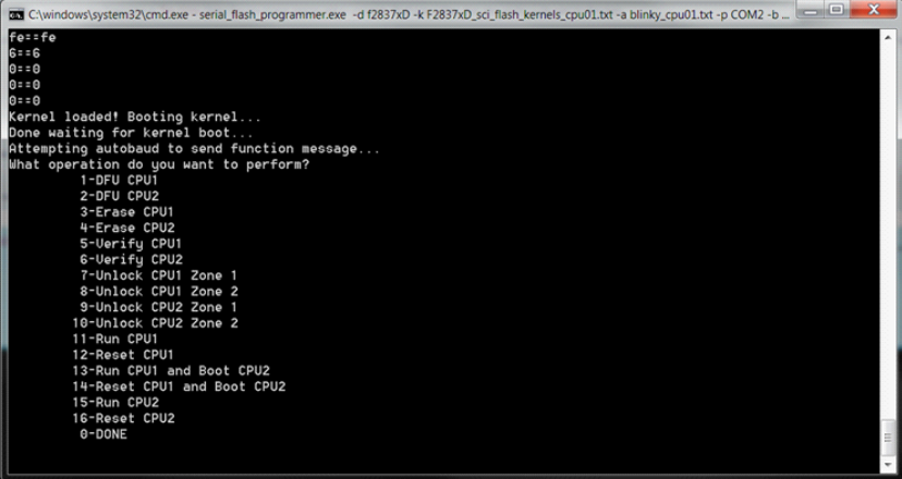
    The command executed is "serial_flash_programmer.exe  -d f2837xD -k F2837xD_sci_flash_kernels_cpu01.txt -a blinky_cpu01.txt -p COM25 -b 9600".

    It seems that the kernel is downloaded but not started as shown below.

    According to sprabv4a, it should print the options to the screen to let the user to choose command like this.

  • Hi Vesgine,

    Thank you for looking into the serial flash programmer and the documenation.

    The kernel you downloaded first in the serial flash programmer was F2837xD_sci_flash_kernels_cpu01.txt. This is the F2837xD_sci_flash_kernels_cpu01.out converted to hex file format for SCI bootloader communication. This F2837xD_sci_flash_kernels_cpu01 is available in controlSUITE to compile and modify. Currently, the file you are using is the compiler and converted kernel which used GPIO 28/29 for SCI communication. That is why it is not working properly right now.

    You are downloading the kernel using GPIO84/85 properly using SCI_BOOT2, but then the kernel is executing and expecting to use GPIO 28/29 so, the autobaud and the communication between the PC (serial flash programmer) and the device (kernel) is not working properly.

    In the kernel, there is a function call SCI_Boot(BOOT_MODE); Change the parameter to SCI_Boot(BOOT_MODE_ALT);

    The above are not the exact names of the parameters, but you will see what I mean when you look at the code.

    Compile the kernel to use GPIO85/85 (ALT) and then use the .txt which is converted from the .out in the project.

    This should work.

    sal
  • Hi Sal

    Great! Your suggestion is right!
    I finally get this problem solved thanks to you. The C2prog only supports GPIO84/85 option.

    Vesgine
  • Hi Sal,
    Sorry for bringing this thread up again but I am running into the same problem. I've followed this thread up until now and not sure what's next. I have changed the code in the F2837xD_sci_flash_kernels_cpu01 project from:
    EntryAddr = SCI_GetFunction(SCI_BOOT);
    to
    EntryAddr = SCI_GetFunction(SCI_BOOT_ALTERNATE);
    and get the F2837xD_sci_flash_kernels_cpu01.txt and then what? Do I need to put this file somewhere in the C2Prog folder to replace the old file, which I couldn't find? Please advise. Thanks!
  • Those sci flash kernels do not work with C2Prog, but they work with the serial flash programmer which is available in controlSUITE and c2000Ware.

    Please see http://www.ti.com/lit/sprabv4

    sal
  • Thanks Sal,

    I might have misunderstood your previous statement. It was actually solution to the serial flash programmer issue and not to the C2Prog issue opened by the OP. I've been trying to get the C2Prog to work with the F2837xD controlCard and got stuck at 

    I have contacted CodeSkin for the solution but any info here would be helpful. Thanks again...

  • ED,

    We do not support CodeSkin. if you have any other questions regarding serial flash programmer, sci kernels, or questions regarding the devices, please post a new thread on this forum.

    You may be using the wrong GPIO pins or SCI boot mode with C2Prog. I am not sure.

    Thanks,
    sal
  • If you are still having problems with C2Prog, please open a new thread and another engineer may be able to help.
    Thanks,
    sal
  • I just got a reply from CodeSkin saying they don't have a solution to this (C2Prog working with F2837xD controlCard). I will make recommendations to use GPIO84/GPIO85 when we lay out the board. That should hopefully resolve the issue. Thanks.