This thread has been locked.

If you have a related question, please click the "Ask a related question" button in the top right corner. The newly created question will be automatically linked to this question.

GPIO interrupt question for TMS320F2812

Other Parts Discussed in Thread: TMS320F2812, CCSTUDIO, SPRC097

Hi,

I have a question regarding which variable to use to setup an interrupt for one of my GPIO line in TMS320F2812

I've successfully setup an interrupt for SCI-A before using PieVectTable.RXAINT and it works fine.

I just need to know what to use to setup an interrupt for GPIO for example GPIO B3

Any help will be greatly appreciated.

Thank you so much

  • Hi Kevin,
    Are you using SYS/BIOS or TI-RTOS?
    Thanks,
    Janet
  • Hi Janet,

    I'm not sure what do you mean by that, sorry.

    Can you please elaborate the question?

    I'm just using CCStudio v.3.3 right now

  • Hi Kevin,

    Then you must not be using SYS/BIOS.  This forum is for TI-RTOS and SYS/BIOS software related questions.  You might try posting your question to a device forum, such as:

    Hopefully someone monitoring that forum can answer your question.  I will see if I can get this post moved to the appropriate forum.

    Best regards,

    Janet

  • I've moved your thread to the device forum.

    Todd
  • Kevin,
    If I have understood your concern correctly, you would like to generate an interrupt based on activity in one of the GPIO pins. There is no "GPIO interrupt" as such. What you could do is to use the XINT1 (GPIOE0) or XINT2 (GPIOE1) interrupts. In F2812, these interrupts are tied to the indicated GPIO pins.
  • Hi Hareesh,

    Thanks for the explanation. I'm now reading this section.

    So just to clarify and more questions:
    1. There is no way to setup an interrupt for individual GPIO line?
    2. What is XNMI/XINT13?
    3. If your answer to #1 is No, is there a way to setup interrupt for individual GPIO line through event manager?
    4. Do you have any example to calculate RPM of a fan? My question regarding GPIO interrupt is to calculate this

    Thank you so much for your help
  • 1. There is no way to setup an interrupt for individual GPIO line?

    Answer: No. Not solely as a GPIO.


    2. What is XNMI/XINT13?

    Answer: It is just another interrupt, but doesn't come under the purview of the PIE.


    3. If your answer to #1 is No, is there a way to setup interrupt for individual GPIO line through event manager?

    You could use the Capture module.


    4. Do you have any example to calculate RPM of a fan? My question regarding GPIO interrupt is to calculate this

    Answer: Please explore the suitability of using the Capture module. Look for examples in SPRC097.

  • RPM of a fan....
    - If you have an input that generates a toggle for every rotation of the fan, then Capture module can help.

    Ramesh
  • Hi Hareesh,

    I couldn't find any info regarding capture module from the link that you gave me. Any advice?
  • Can you please elaborate this capture module? I couldn't find any info from the link that Hareesh gave me
  • You will find eCAP info here below

    www.ti.com/.../sprufz8a.pdf

    eCAP will help to capture the time between two edges. That is why in my prev post, I mentioned that if your application generates a bit toggle corresponding to motor speed, you can calculate RPM.
  • Thank you! I'll start reading that. Meanwhile, do you have any sample code on how to setup the capture module? I've read the steps on how to set it up but just wondering if there's any sample code out there. If you have sample code that's directly related to calculating RPM, that will be great.

    Another question: why can't I just use XINT1 or XINT2? What's the benefits of using capture module?
  • Kevin,

    Since you are using F2812, which has the Capture module (and not the eCAP), the document you need to refer is  

  • Hi Hareesh,

    Thank you for the info, that saves my time.

    Can you please explain to me what's the benefit of using capture module compared to a normal GPIO interrupt (XINT1/XINT2)?

    Thank you so much
  • The eCAP hardware does some tasks automatically, which will need to be done by software, if you are using GPIO.
  • Hi Hareesh,

    Sorry for the very late reply,

    I have question regarding XINT1CR (external interrupt 1 control register)

    It has a polarity field which determine whether interrupt generated on a falling edge (high to low) or rising edge (low to high) transition.

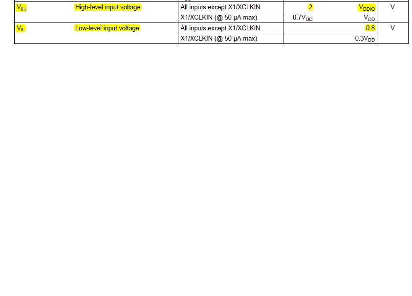
    What is the voltage level for this "high" and "low" criteria? 

    Or any falling edge is considered fine. Like for example 0.2V to 0.1V is consider a falling edge?

    Thank you for the answer

  • Please look at section 6.2 in page 91 of SPRS174T. For a signal to be recognized as a logic-low or logic-high (and for the transitions between them to be recognized), the input signals must meet the VIH/VIL ranges stated in that table.

  • HI Hareesh,

    I want to try using XINT1 first. And this is what I currently have:

    void xint1_isr_init()
    {
    GpioMuxRegs.GPEMUX.bit.XINT1_XBIO_GPIOE0 = 1; // peripheral functionality
    GpioMuxRegs.GPEDIR.bit.GPIOE0 = 0; // set as input??
    XIntruptRegs.XINT1CR.bit.POLARITY = 1; // we can try 0 later, right now rising edge
    XIntruptRegs.XINT1CR.bit.ENABLE = 1; // enable interrupt
    GpioDataRegs.GPBDAT.bit.GPIOB13 = 0; // turn off LED
    interruptcounter = 0;
    }
    interrupt void xint1_isr (void)
    {
    interruptcounter++;
    // blink most leftside LED so we can see what's going on
    if (GpioDataRegs.GPBDAT.bit.GPIOB13)
    GpioDataRegs.GPBDAT.bit.GPIOB13 = 0;
    else
    GpioDataRegs.GPBDAT.bit.GPIOB13 = 1;
    }
    with this enable as well:
    PieVectTable.XINT1 = &xint1_isr;
    PieCtrlRegs.PIEIER1.bit.INTx4 = 1; // This is PIE Group 1, INT4 = XINT1
    IER |= 0x001; // enable group 1 int for XINT1
    Basically I want GPIOB13 to blink whenever XINT1CR have event interrupted.
    For some reason it only get into the interrupt once.
    Do I need to clear the interrupt or is there anything wrong that I do?
    Can you please advice? Thank you.
  • Kevin,

    Have you checked out sec 6.1 of SPRU078G? It explains how the PIE needs to be configured. You may also want to look at the interrupt examples that come with the DSP28 header files. Look at the attached file for an example of how interrupts are handled.

    Example_281xSpi_FFDLB_int.c
    // TI File $Revision: /main/4 $
    // Checkin $Date: July 2, 2007   11:27:41 $
    //###########################################################################
    //
    // FILE:   Example_281xSpi_FFDLB_int.c
    //
    // TITLE:  DSP281x Device Spi Digital Loop Back porgram.
    //
    // ASSUMPTIONS:
    //
    //         This program requires the DSP281x V1.00 header files.
    //         As supplied, this project is configured for "boot to H0" operation.
    //
    //         Other then boot mode pin configuration, no other hardware configuration
    //         is required.
    //
    // DESCRIPTION:
    //
    // This program is a SPI example that uses the internal loopback of
    // the peripheral.  Both interrupts and the SPI FIFOs are used.
    //
    // A stream of data is sent and then compared to the recieved stream.
    //
    // The sent data looks like this:
    // 0000 0001 0002 0003 0004 0005 0006 0007
    // 0001 0002 0003 0004 0005 0006 0007 0008
    // 0002 0003 0004 0005 0006 0007 0008 0009
    // ....
    // FFFE FFFF 0000 0001 0002 0003 0004 0005
    // FFFF 0000 0001 0002 0003 0004 0005 0006
    // etc..
    //
    // This pattern is repeated forever.
    //
    //
    // Watch Variables:
    //     sdata[8]    - Data to send
    //     rdata[8]    - Received data
    //     rdata_point - Used to keep track of the last position in
    //                   the receive stream for error checking
    //###########################################################################
    // $TI Release: $
    // $Release Date: $
    //###########################################################################
    
    #include "DSP281x_Device.h"     // DSP281x Headerfile Include File
    #include "DSP281x_Examples.h"   // DSP281x Examples Include File
    
    // Prototype statements for functions found within this file.
    // interrupt void ISRTimer2(void);
    interrupt void spiTxFifoIsr(void);
    interrupt void spiRxFifoIsr(void);
    void delay_loop(void);
    void spi_fifo_init(void);
    void error();
    
    Uint16 sdata[8];     // Send data buffer
    Uint16 rdata[8];     // Receive data buffer
    Uint16 rdata_point;  // Keep track of where we are
                         // in the data stream to check received data
    
    void main(void)
    {
       Uint16 i;
    
    // Step 1. Initialize System Control:
    // PLL, WatchDog, enable Peripheral Clocks
    // This example function is found in the DSP281x_SysCtrl.c file.
       InitSysCtrl();
    
    // Step 2. Initalize GPIO:
    // This example function is found in the DSP281x_Gpio.c file and
    // illustrates how to set the GPIO to it's default state.
    // InitGpio();  // Skipped for this example
    // Setup only the GP I/O only for SPI functionality
       EALLOW;
       GpioMuxRegs.GPFMUX.all=0x000F;	// Select GPIOs to be SPI pins
                                        // Port F MUX - x000 0000 0000 1111
       EDIS;
    
    // Step 3. Initialize PIE vector table:
    // Disable and clear all CPU interrupts
       DINT;
       IER = 0x0000;
       IFR = 0x0000;
    
    // Initialize PIE control registers to their default state:
    // This function is found in the DSP281x_PieCtrl.c file.
       InitPieCtrl();
    
    // Initialize the PIE vector table with pointers to the shell Interrupt
    // Service Routines (ISR).
    // This will populate the entire table, even if the interrupt
    // is not used in this example.  This is useful for debug purposes.
    // The shell ISR routines are found in DSP281x_DefaultIsr.c.
    // This function is found in DSP281x_PieVect.c.
       InitPieVectTable();
    
    // Interrupts that are used in this example are re-mapped to
    // ISR functions found within this file.
       EALLOW;	// This is needed to write to EALLOW protected registers
       PieVectTable.SPIRXINTA = &spiRxFifoIsr;
       PieVectTable.SPITXINTA = &spiTxFifoIsr;
       EDIS;   // This is needed to disable write to EALLOW protected registers
    
    
    // Step 4. Initialize all the Device Peripherals:
    // This function is found in DSP281x_InitPeripherals.c
    // InitPeripherals(); // Not required for this example
       spi_fifo_init();	  // Initialize the SPI only
    
    
    // Step 5. User specific code, enable interrupts:
    
    // Initalize the send data buffer
       for(i=0; i<8; i++)
       {
          sdata[i] = i;
       }
       rdata_point = 0;
    
    // Enable interrupts required for this example
       PieCtrlRegs.PIECRTL.bit.ENPIE = 1;   // Enable the PIE block
       PieCtrlRegs.PIEIER6.bit.INTx1=1;     // Enable PIE Group 6, INT 1
       PieCtrlRegs.PIEIER6.bit.INTx2=1;     // Enable PIE Group 6, INT 2
       IER=0x20;                            // Enable CPU INT6
       EINT;                                // Enable Global Interrupts
    
    // Step 6. IDLE loop. Just sit and loop forever (optional):
    	for(;;);
    
    }
    
    
    // Some Useful local functions
    void delay_loop()
    {
        long      i;
        for (i = 0; i < 1000000; i++) {}
    }
    
    
    void error(void)
    {
        asm("     ESTOP0");	 //Test failed!! Stop!
        for (;;);
    }
    
    
    void spi_fifo_init()
    {
    // Initialize SPI FIFO registers
       SpiaRegs.SPICCR.bit.SPISWRESET=0; // Reset SPI
    
       SpiaRegs.SPICCR.all=0x001F;       //16-bit character, Loopback mode
       SpiaRegs.SPICTL.all=0x0017;       //Interrupt enabled, Master/Slave XMIT enabled
       SpiaRegs.SPISTS.all=0x0000;
       SpiaRegs.SPIBRR=0x0063;           // Baud rate
       SpiaRegs.SPIFFTX.all=0xC028;      // Enable FIFO's, set TX FIFO level to 8
       SpiaRegs.SPIFFRX.all=0x0028;      // Set RX FIFO level to 8
       SpiaRegs.SPIFFCT.all=0x00;
       SpiaRegs.SPIPRI.all=0x0010;
    
       SpiaRegs.SPICCR.bit.SPISWRESET=1;  // Enable SPI
    
       SpiaRegs.SPIFFTX.bit.TXFIFO=1;
       SpiaRegs.SPIFFRX.bit.RXFIFORESET=1;
    }
    
    interrupt void spiTxFifoIsr(void)
    {
     	Uint16 i;
        for(i=0;i<8;i++)
        {
     	   SpiaRegs.SPITXBUF=sdata[i];      // Send data
        }
    
        for(i=0;i<8;i++)                    // Increment data for next cycle
        {
     	   sdata[i]++;
        }
    
    
        SpiaRegs.SPIFFTX.bit.TXFFINTCLR=1;  // Clear Interrupt flag
    	PieCtrlRegs.PIEACK.all|=0x20;  		// Issue PIE ACK
    }
    
    interrupt void spiRxFifoIsr(void)
    {
        Uint16 i;
        for(i=0;i<8;i++)
        {
    	    rdata[i]=SpiaRegs.SPIRXBUF;		// Read data
    	}
    	for(i=0;i<8;i++)                    // Check received data
    	{
    	    if(rdata[i] != rdata_point+i) error();
    	}
    	rdata_point++;
    	SpiaRegs.SPIFFRX.bit.RXFFOVFCLR=1;  // Clear Overflow flag
    	SpiaRegs.SPIFFRX.bit.RXFFINTCLR=1; 	// Clear Interrupt flag
    	PieCtrlRegs.PIEACK.all|=0x20;       // Issue PIE ack
    }


    //===========================================================================
    // No more.
    //===========================================================================


  • Hi Hareesh,

    I've read that hence I configured the PIE:

    PieVectTable.XINT1 = &xint1_isr;
    PieCtrlRegs.PIEIER1.bit.INTx4 = 1; // This is PIE Group 1, INT4 = XINT1
    IER |= 0x001; // enable group 1 int for XINT1
    I know the interrupt is working ONCE, but for some reason it never get it again after the first one. Hence my question
  • Are you writing to the PIEACK inside the ISR? Refer the example I had attached in the previous post. Modify the group to reflect XINT1.
  • Hi Hareesh,

    Thanks a lot for the help.

    This might gonna be the last question:

    For the XINT1 should I follow 0.3 * 1.8V for V_IL and 0.7*1.8V for V_IH

    Or 0.3 * 3.3V for V_IL and 0.7 * 3.3V for V_IH

    Because according to the manual, all GPIO pins are 3.3 V but supply is 1.8 V

    Can you please confirm this for me? I'm using that XINT1 pin as peripheral not GPIO.

  • Kevin,

    As shown in the datasheet, all I/O pins operate at 0-3.3v level (regardless of whether they are used for GPIO functionality or peripheral functionality). So you will use the 3.3v values.

  • Hi Hareesh,

    Thanks for the clarification.

    Will it be safe if let's say I have -0.3V as my VIL, what's the lower limit of VIL?

  • Hi Hareesh,

    Thank you so much it's working now.

    How do I measure exactly 1 second with my DSP? Can you please give me an example? Thank you so much

  • Kevin,

    Please open a new thread with the correct subject line, so that the appropriate experts will answer your question.