This thread has been locked.

If you have a related question, please click the "Ask a related question" button in the top right corner. The newly created question will be automatically linked to this question.

About the motor specifications of TI's 2MTR-DYNO InstaSPIN-FOC Evaluation Module

Other Parts Discussed in Thread: 2MTR-DYNO

Hello Everyone,

I am currently seeking to buy some equipment for motor control experiment and I am interested in TI's "2MTR-DYNO InstaSPIN-FOC Evaluation Module" (www.ti.com/.../2MTR-DYNO

To guarantee that I made the right choice, I want to test the control performance of my designed controller on this motor first using Simulink.  However, after looking both TI’s website and the datasheet provided by Teknic (according to TI’s website, the motor included in this evaluation module is Teknic’s M-2310P-LN-04K), I was unable to find the necessary specifications of this motor to start my simulation.

The datasheet of the M-2310P-LN-04K can be found at the following website:

https://www.teknic.com/files/product_info/N23_Industrial_Grade_Motors_v6.3.pdf


It provides me with the following information

Motor Poles:                                      8

Resistance, phase to phase             2.87 Ohm

Inductance, phase to phase             1.61 mH

Electrical Time Constant                   0.56 ms

Back EMF Constant                          9.28 Vpeak/kRPM


Based on these information, I am able to calculate the following motor specifications

Pole Pairs                                               4

Stator Phase Resistance                       1.435 Ohm

Armature Inductance                              0.00161 H

Flux Linkage established by magnets    0.018089 V.s


However, I am unable to acquire the following motor parameters which are necessary for my simulation

Rotor Inertia                                      kg.m2

Viscous Damping                              N.m.s

Rated Current                                   A

Rated Voltage                                   V


I know that the best way is to buy this product and measure it by myself.  But the controller I designed is highly sensitive to sampling time.  The minimum sampling time supported by the ADCs on my dsp board is 1 ms.  If later I found that I need a sampling time less than 1 ms to control this M-2310P-LN-04K motor, it would be a waster for me to buy this product.  I have very limited budget for my experiment and I don’t want to waste it.


The experiment I need to finish is crucial for my Ph.D. thesis and is very important to me.  If anyone here can help me figure out how to acquire the above motor specifications, I would really appreciate your help.

  • Teknic would be the best resource to answer the questions about the motor

    but I don't see what the missing values has to do with your sampling time
  • Hi ChrisClearman,

    Thank you. I have emailed Teknic and still waiting for their response. I was hopping if someone here has bought this product before and has the information I need.

    Sorry, I didn't explain this clearly. I have designed a controller and I need to verify its effectiveness through experiment. Depending on the parameters of the motor, the sampling time required for my control algorithm is different (the controller gain is also important).

    Thank you again for your help.
  • I still don't see how those values will effect the sampling time....but ok.

    I'm pretty sure the motors are rated for >60V, 7.1A continuous, and 6 KRPM
    4.6 V/KRPM, 38.8 oz-in

    inertia and damping are not provided in any material I have access too
  • I'm sorry for the confusion.

    My controller is adaptive control based.  At each sampling time, the controller will update its output.

    If the nonlinear behavior of a motor were to be studied, a small sampling time is necessary to guarantee controller's performance.  If you familiar with adaptive control, think about how you pick the sampling time and step size to control a nonlinear system.

    Thank you very much for the information you have provided.  It helps me figure out a mistake I have made.

    The electrical interface of this 2MTR-Dyno is P type but the motor specifications I provided before are from motors whose electrical interface is S/E/W type.

    Thank you again for your help.

  • I have received responses from Teknic and they have provided me with the parameters that I need.

    This motor's rotor inertia is 0.001 oz-in-s^2.

    0 Ohm Damping 42.51 oz-in/kRPM.

    Thank you for your help.

  • thanks for posting in case someone else needs them in the future
  • Hello,

    First a big thanks for posting this, these were exactly the values I was looking for. However I would like to be sure that these are the values for the M-2310P-LN-04K, because the specs you posted in the first place correspond to the M-2310(S/E/W) motors. Could you clarify? Thanks!

    Best regards,

    Nam

  • Hello Nam,


    The specs I posted in the first place is wrong.  It corresponds to M-2310 (S/E/W).  I've mentioned this a few posts before.


    However, the rotor inertia and damping I provided correspond to M-2310P-LN-04K.  You can acquire the rest specs from Teknic's product manual.

  • Thanks for your answers! The simulation now works like a charm.

    Best regards,

    Nam

  • Hi ChrisClearman,

    I’m planning to use the 2MTR-DYNO InstaSPIN-FOC Evaluation Module, BOOSTXL-DRV8305EVM, and F28379D LaunchPad to establish a motor control system in order to verify my controller design.

    However, I’m confused about the rated current of the Permanent Magnet Synchronous Motors included in the 2MTR-DYNO InstaSPIN-FOC Evaluation Module.

    The motor is Teknic M-2310P-LN-04K. I used the following motor specifications acquired from Teknic and run a simulation test in Simulink.

    In my simulation, I found that in order for the motor to run at 5000 rpm, which is its maximum speed, I have to apply a three phase voltage source of 60 Volts, 333 Hz.  The resultant stator current has a peak value of 50A, which means a continuous current of 35A (rms value).  This is quite different from the 7.1 A rated continuous current you have mentioned.

    The BOOSTXL-DRV8305EVM only supports applications with 4.4V to 45V voltage input and 20A peak, 15 A continuous current output.  If my simulation results are right, this means it can only control the 2MTR-DYNO InstaSPIN-FOC Evaluation Module to run at low speed range, which does not meet my experiment requirement.

    I’ve read some articles in your blog (like “Designing for rapid dual-axis motor control development”) and found you have some demonstration examples, which use BOOSTXL-DRV8305EVM to control the 2MTR-DYNO InstaSPIN-FOC Evaluation Module.

    Since you have the hands on experience with these two components, could you please tell me if the BOOSTXL-DRV8305EVM is capable of controlling the 2MTR-DYNO InstaSPIN-FOC Evaluation Module to run at high speed?

    Thank you.

  • your simulation is wrong.

    you can run this motor at 5 KRPM with much lower continuous current, depending on the torque you need to produce.
    I haven't tested the current requirements for full load, but Teknic would know best.

    it says right on the label 7.1A continuous and 38.8 oz-in of torque (which probably requires higher peak current)
  • Hi ChrisClearman,

    Thank you very much for your clarification. I'll give up simulation and go directly to experiment test.

    Thank you for your time.
  • Hello everyone,

    I am back after a few months since I ran into a problem of power consumption similar to the one faced by Uponmoon. I post the solution here in case someone needs it.

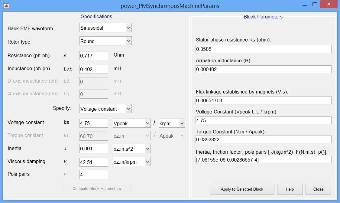
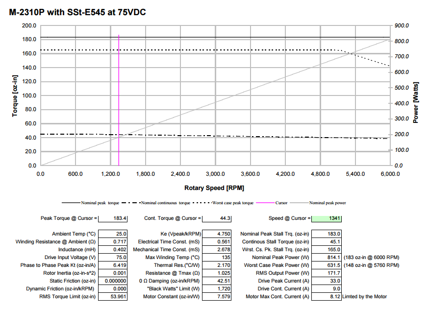
    First the motor characteristics, kindly provided by Teknic:

    The 0 Ohm damping is NOT the setting asked by Simulink, despite the name similarity. The 0 Ohm damping is the damping caused by magnetic induction which fights the motor movement (Faraday's law of induction). This can be computed directly from Ke and Kt: Dm = Ke*Kt / R, with normally Ke = Kt, so Simulink does not need it as an input.

    What Simulink expects here is actually the damping due to friction forces (dynamic friction). Using the 0 Ohm damping value instead results in a big friction force in the simulation which increases significantly the power needed to run the motor, hence the excessive currents.

    Teknic says the dynamic friction factor is null. However, after testing a little bit, I came to the conclusion that the actual dynamic friction is not as null as Teknic says. I personally set the dynamic friction to approximately 0.000125 Nm.s (about 1.8537 oz-in/kRPM) to make it work. This is a purely EMPIRICAL value but which shows good results in my test system. It is however not impossible that the friction actually comes from something else in my system, making the value valid only for my case.

    I hope this helps.

    Best regards,

    Nam

  • I have no idea why my post landed in this thread. This belongs to the thread e2e.ti.com/.../1993276, sorry for the inconvenience.
  • Hi Nam,

    Thank you for clarifying the definition of 0-ohm damping.

    I'm not sure how you managed to match the current with the rated motor current in your simulation.  I've contacted Teknic, for this specific motor (M-2310P-LN-04K), the 'P' stands for "parallel wye connected winding", which is different from the common series wye connected winding.

    I failed to get more detail on this from Teknic so I did some search online by myself.  There is very limited resources for this topic and this link might be helpful for you to understand the difference.

    what-when-how.com/.../

    Based on my understanding, since this motor has 8 poles, then it means in each phase it has 8 coils (assume each coil stands for a single pole) in parallel.  If you are using the standard stator d-q reference frame based PMSM model for your simulation, then after you use the inverse dq transformation and get the phase current for each phase (I_as, I_bs, and I_cs), you have to divide this value by 8 (Because this phase current is the summation of the currents flowing in all 8 coils).

    This is just my understanding and I didn't verify it through experiment yet.  I'm a newbie for this and I'm currently still playing with the TI lauchpad.  If you were able to verify it, please let me know the results.

    Thanks.

  • Hi,

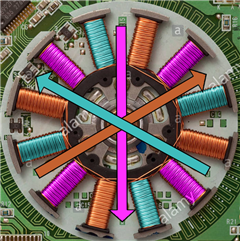
    From my understanding the internal architecture of the windings does not matter (in most / high-level cases). The windings are organized so they create a magnetic field in the same direction as if they were only three. Here an example with 12 windings:

    (This is a possible configuration, not necessarily the real one - and sorry for the copyright)

    Here the windings of the same color are connected together and create a magnetic field in a specific direction. All directions have an angle difference of 120°, exactly like if there were only 3 windings. The number of magnet poles is irrelevant, it does not have to match the number of windings.

    Now for the inductances values, I expect / hope that the manufacturer provides values which represent the behavior of all inductances together, possibly including mutual inductance effect (e.g. in series L = L1 + L2 - 2M, in parallel L = (L1.L2 - M²) / (L1 + L2 + 2M)). So from an external point of view, the windings organization is generally irrelevant.

    I hope this helps.

    Best regards,

    Nam

  • Hi Nam,

    Thanks for the explanation.  The figure you used seems more like a winding configuration for a brushless DC motor with trapezoidal back emf.  For PMSM with sinusoidal back emf, the winding is actually sinusoidally distributed and it is difficult to tell which coil belongs to which phase if you simply look inside the motor stator.

    But, yes, you are right.  I think I went to the wrong direction.  The terminal current should be rated current of the motor.  The current flow through each pole does not matter for the simulation.  It only influences the torque generation capability of the motor. 

    I think the phase to phase inductance provided by Teknic is directly measured from the terminal, which means it represents the behavior of all inductances together.  I've tried to used the viscous damping coefficient you provided, and I still got a phase current like 100A.

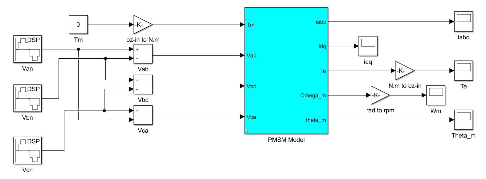
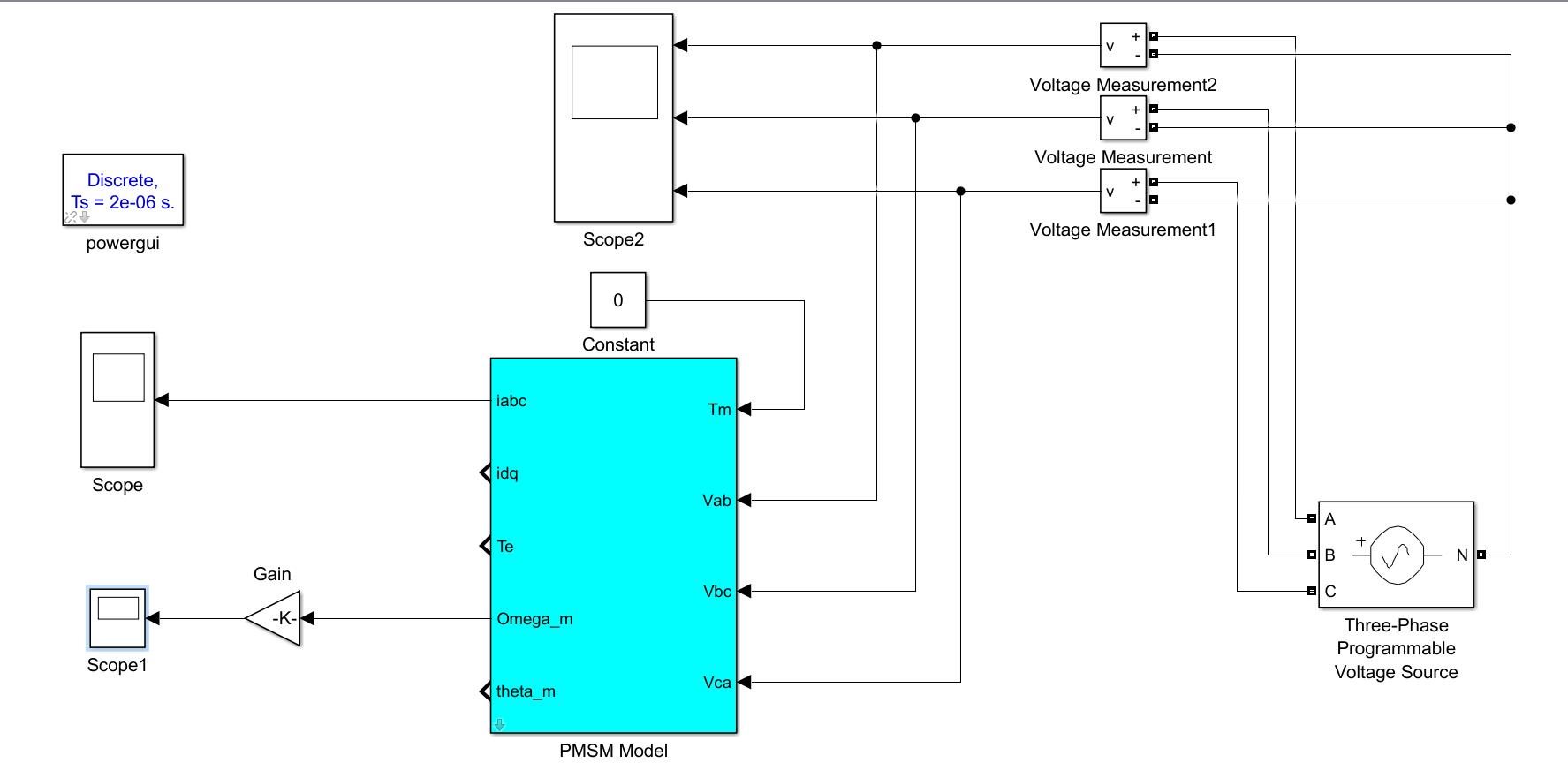
    I have used the following simulation scheme to test the motor behavior.  The PMSM model is first established under d-q reference frame, and then I used the dq-transformation and inverse dq-transformation to transfer it back to the stationary abc reference frame.  

    The motor parameters are

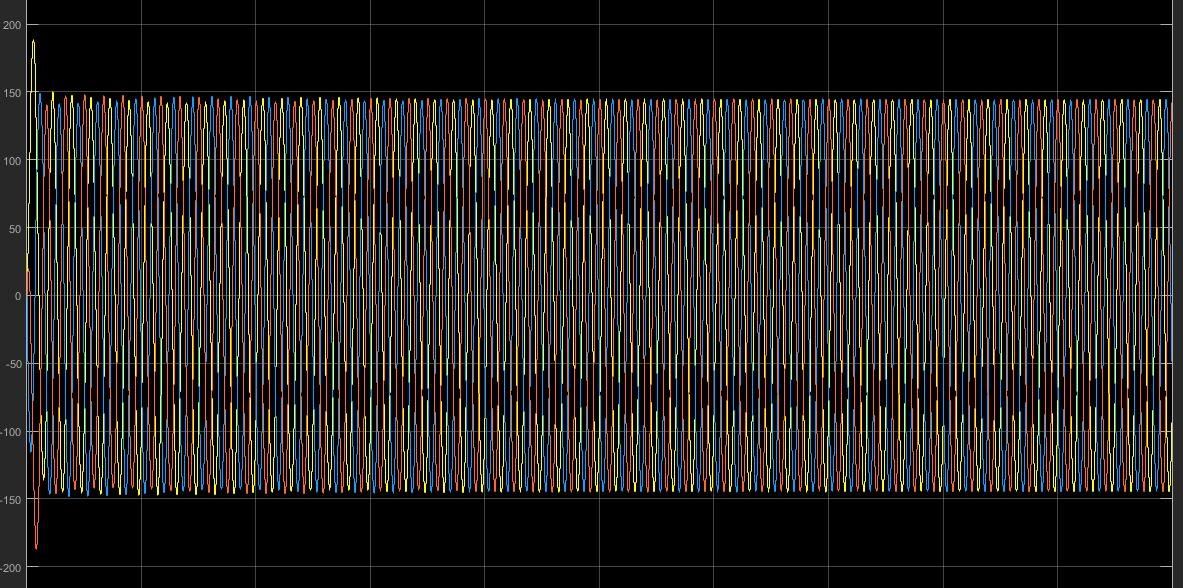
    I've supplied the motor with 75V (peak value) 300HZ AC voltage and the phase current I got is kind of crazy.

    What happens in your case? 

    Thanks for the help.

  • Hi,

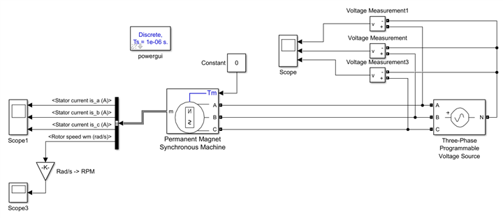
    Sorry for the delay I was a little bit busy. In my case I use a Field-Oriented Controller I designed myself for my company, so it will be little help to you. But I do have a simulation of a basic functioning with a 3-phases power supply.

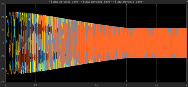
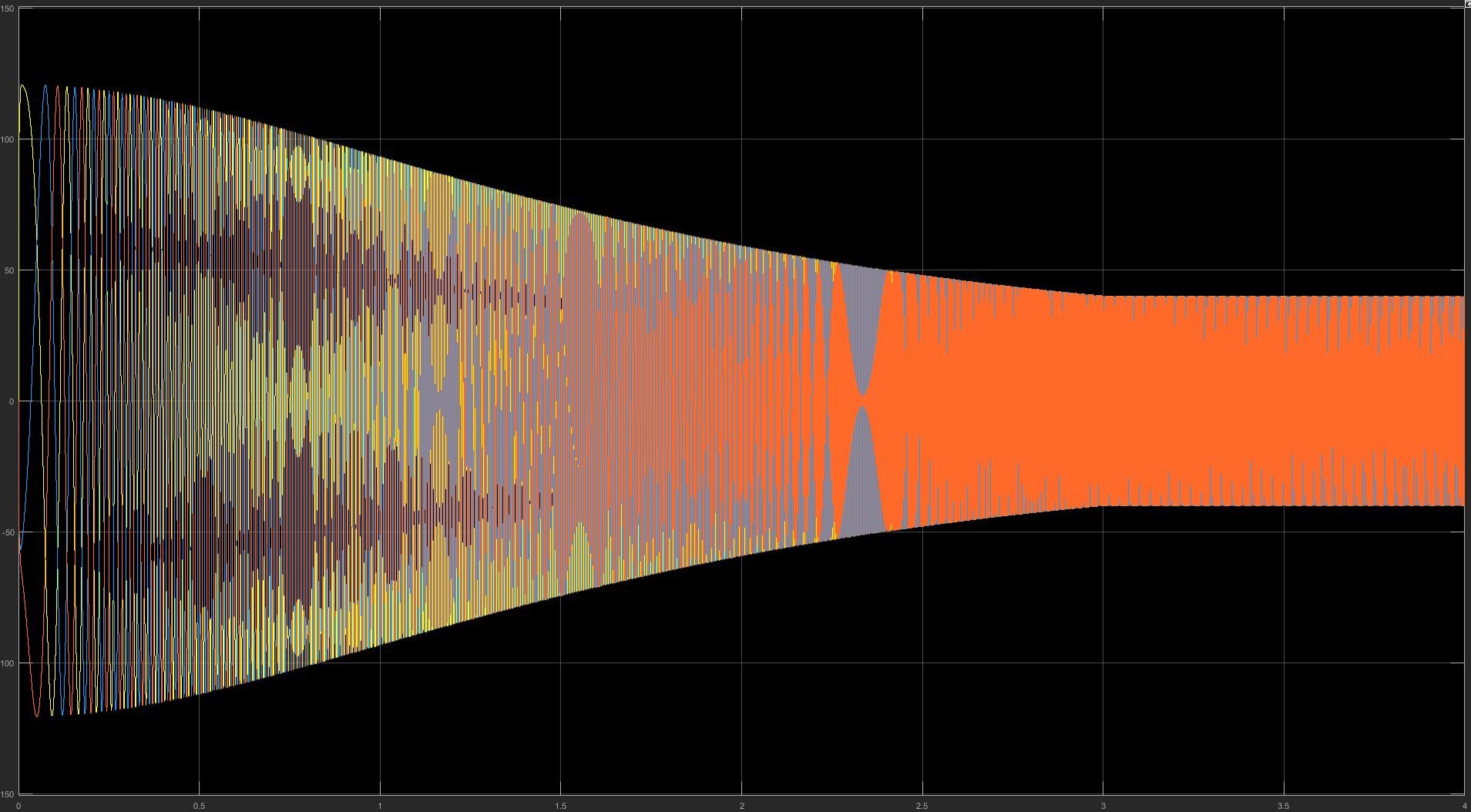
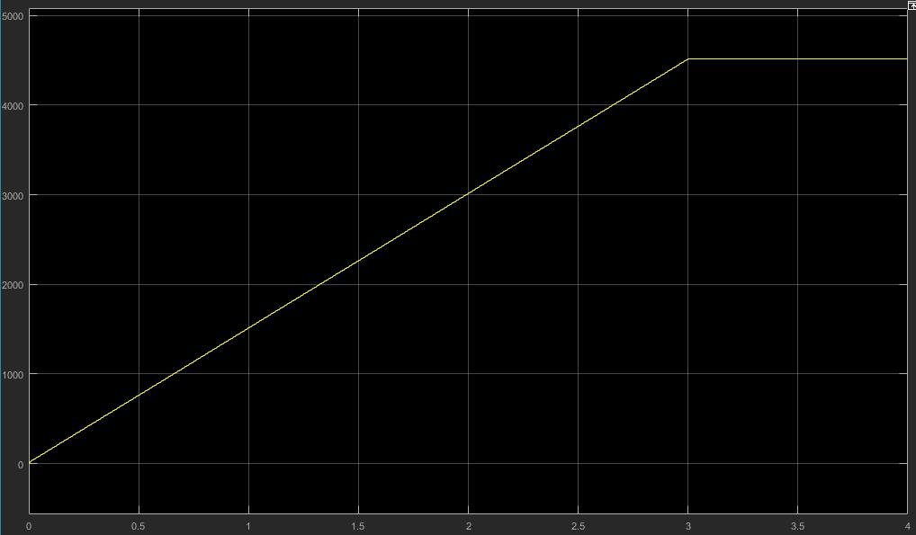
    I set it up at about 75 Vpeak ph-ph with a frequency increasing from 0 to 200 Hz in 2 secs, in order to let the motor start. Here is the current consumption on all phases:

    As you can see the current consumption starts high and then decreases when the motor speed increases. Are you sure your motor is actually moving? Personally at 300 Hz my motor stalled after a few seconds. I'm not sure why though.

    Of course the currents are still much higher than what the motor could actually support, but at this voltage and given the back-EMF voltage constant (4.75 V/kRPM, so here at 3000 RPM we have 14.25 V of back voltage only), it's not surprising. 

    In my case the Field-Oriented Controller adjusts the currents continuously in function of the torque needed, so the currents stay low. I believe TI uses a similar (but much more advanced) system (www.motionsolutions.net/.../SSt-E545-RCx-659p3460.htm). A FOC makes your motor behave more or less like a DC motor, which simplifies everything.

    Best regards,

    Nam

  • Hi Nam,

    Thank you for your help.  In my case, I have designed my own motor control algorithm and I want to verify its effectiveness through both simulation and experiment.  Below is the motor's nameplate.

    As you can see the motor is designed to run at 7.1A continuous current.  But in your simulation, its about 50A.  This is a large difference and it means the simulation results and experiment results are not comparable.   I'm still trying to limit the simulated motor current to be close to 7.1A but make no progress yet.  Do you have any idea on this?  

    I initially thought since this motor is parallel-wye connected, I could divide the simulated phase current by 8 (cause the motor have 8 poles) and get the current flow in each pole.  But that still means I have to supply the motor with 50A to the motor input terminal, which doesn't make sense.

    For the simulation you provided, I didn't consider the initial start issue in my simulation since I just want to verify the accuracy of the motor model.

    I built the same system in Simulink as you showed.  And yes, the motor do not behavior properly at 300HZ.  Actually, this is the why I didn't use the PMSM model provided by Simulink Simcap toolbox.  The problem with this PMSM model block is that if you uses the built-in preset model provided by this Simulink block, you will found everything runs perfect.  But if you use your own motor parameters, you will always get some weird results and I don't know the reason yet.

    Below is the simulation scheme I used which uses a PMSM model I built with basic simulink blocks (you could right click on your simcap PMSM model and select mask - look under mask.  Copy the electrical model and mechanical model inside the mask and use them as a template).

    The current and speed responses are

    Hope it helps, Thanks

  • Hi,

    Like I said, with such high voltages the currents will necessarily be high. You should try with a voltage of around 30 V ph-ph RMS or even lower. Of course, the stall torque will then be lower too, but at least the motor will survive. If you need more torque, consider buying a bigger motor.

    In the TI measurements, 75 V is the voltage of the driver supply, not the voltage of the motor. The driver probably uses a FOC with PWM or something similar to control the maximal voltages / currents in the motor phases.

    Best regards,

    Nam

  • Hi,

    OK. I'll try it.

    Thanks.

  • Dear Uponmoon,

    I've have testing the motors in 2MTR-DYNO in my project. So that I can share you some information:

    1. The data got from datasheet  is only for reference purpose. It's only the rated values.

    2. I ran Lab2a or Lab2b to identify the motor parameter and below is the result of motor ID:

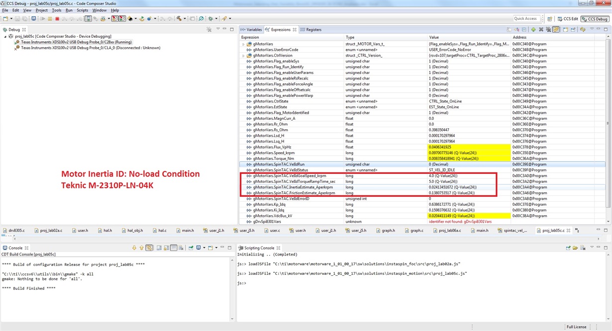
    3. The inertia of a couple of motors was estimated by running Lab5c or Lab 12a and the its result is below:

    4. I controlled these motors at VdcBus = 20V with BOOST-8305DRV and LaunchPad-F28069M, and I found that the maximum speed that I reached is 3600 RPM. If I use over-modulation (Lab 10a) the speed of motor can reach to above 4000 RPM.

    So that, I think if you supply the inverter by a VdcBus = 36V or more, the speed of the motor can increase above these values.

    5. I also built a simulation model in PLECS environment (that is similar to Simulink/Matlab) and get the same results as experience.

    Hope to help!


  • Hi Duong,

    Thank you very much for the information you have provided.

    I tried Lab5 and Lab12 using my own M-2310P-LN-04K and got very similar results as yours.

    But, I have some doubt about the friction conversion.

    TI only provide a formula in section 10.5 of "InstaSPIN-FOC™ and InstaSPIN-MOTION™ User's Guide", which converts the inertia into SI unit. There is no formula to convert the friction.

    In my understanding, the mechanical equation for a PMSM is J(dw/dt) = Te - Bw - TL, where w is the rotor speed, Te is the electromagnetic torque, B is the viscous damping coefficient, TL is the load torque.

    I think the identified friction should be this B, which is the viscous damping coefficient. But it could also be a static friction coefficient. I'm not sure.

    I didn't find a way to convert the identified friction into SI unit, could you please tell me how you address this issue in your project?

    Thank you very much.
  • Dear Uponmoon,

    I've ever had the same question like you about a formula to convert the estimated inertia & friction by SpinTAC Velocity ID (Lab12a). According to Adam Reynolds's guide (a Solution Architurer from LineStream Technologies), you can find the answer for this issues on Page 386&387, Section 10.5: Bypassing Inertia Estimation of the document #SPRUHJ1F (InstaSPIN-FOC and InstaSPIN-MOTION: User's Guide).

    Hope to help,
  • Hi Duong,

    Thanks for your help.

    But the documents only provide a formula which converts inertia into SI unit. There is no formula to convert the friction. Any suggestion?

    Thanks.
  • Dear Uponmoon,

    According to my experience, you don't need know exact friction to design the speed loop, only inertia is enough for tuning this loop with approximate gains. Of course, in fact the friction always exists, but its present in a motion control system will help the system have a better damping response in comparison with the system without friction.

    I don't know the formula to convert the friction in SpinTAC to SI unit. You can post your question to InstaSpin forum to ask Adam Raynolds for the answer.

    Good luck,
  • Hi Duong,

    Thank you very much for your help.