This thread has been locked.

If you have a related question, please click the "Ask a related question" button in the top right corner. The newly created question will be automatically linked to this question.

ADC result Code Composer Studio TMS320F28379D

Other Parts Discussed in Thread: TMS320F28379D

Hi all,

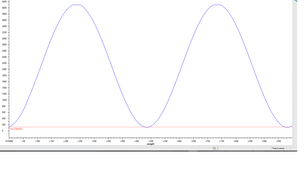
Please I will be glad if anyone can help me trace this problem. I am sampling a 50 Hz Input sinusoidal signal using ADC of TMS320F28379D (Experimenter Kit) and the sampling Frequency is 50kHz. When I graphed the AdcResult, I was expecting to get 1000 samples per period, but I am getting 500 samples per period. Below is the graph from CCS. Also below is the ADC and epwm settings: Thanks in advance for your help.

Note: EALLOW and EDIS were put where necessary. 

AdcaRegs.ADCCTL2.bit.PRESCALE = 14; // Set ADCCLK divider to /8 i.e 25MHZ

AdcaRegs.ADCCTL2.bit.RESOLUTION = 0; // 12-bit resolution

AdcaRegs.ADCCTL2.bit.SIGNALMODE = 0; // Single-ended channel conversions (12-bit mode only)

AdcaRegs.ADCCTL1.bit.INTPULSEPOS = 1; // Set pulse positions to late

AdcaRegs.ADCCTL1.bit.ADCPWDNZ = 1; // Power up the ADC

DELAY_US(1000);// Delay for 1ms to allow ADC time to power up

AdcaRegs.ADCSOC0CTL.bit.CHSEL = 3;  // SOC0 will convert pin A3

AdcaRegs.ADCSOC0CTL.bit.ACQPS = 14; // Sample window is 75ns

AdcaRegs.ADCSOC0CTL.bit.TRIGSEL = 5; // Trigger on ePWM1 SOCA

AdcaRegs.ADCINTSEL1N2.bit.INT1SEL = 0; // End of SOC0 will set INT1 flag

AdcaRegs.ADCINTSEL1N2.bit.INT1E = 1;   // Enable INT1 flag

AdcaRegs.ADCINTFLGCLR.bit.ADCINT1 = 1; // Make sure INT1 flag is cleared


//settings for epwm

EPwm1Regs.TBCTL.bit.CTRMODE = 0; // Count up

 EPwm1Regs.TBPRD = 2000;       // Set timer period for 50 kHz 

EPwm1Regs.CMPA.bit.CMPA = EPwm1Regs.TBPRD / 2; // 50% duty cycle ;

  EPwm1Regs.TBCTL.bit.PHSEN = 0;    // Disable phase loading

   EPwm1Regs.TBPHS.bit.TBPHS = 0x0000;       // Phase is 0

   EPwm1Regs.TBCTR = 0x0000;                  // Clear counter

   EPwm1Regs.TBCTL.bit.HSPCLKDIV = 0;   // HSPCLKDIV = 1

   EPwm1Regs.TBCTL.bit.CLKDIV = 0; // CLKDIV = 1

  • Joseph,

    This is not the problem, but one thing I notice is that you're setting ADCCTL2.PRESCALE to 14 (which is /8), so you are running the ADC at 25 MHz.  ADC is capable of running at 50 MHz.  Any particular reason you are running at only 25 MHz?

    This is also not the problem, but I see this in your code:

    EPwm1Regs.TBPRD = 2000;       // Set timer period for 50 kHz 

    In up-count mode, you should set the period to count-1 (e.g., 1999).  This is because zero is the first count, so you count from 0 to 1999.  That is 2000 counts.

    Also, you should disable the ePWM counter, configure it, and then enable it.  You have it enabled from the start.  This however is also not the problem.  Just pointing out a few things.

    So to the problem, how do you have ePWMxRegs.ETPS.bit.SOCAPRD set?

    What I would do is output the PWM signal on a pin, and confirm frequency on a scope.  Perhaps the clocks are not setup the way you think they are.  I'd start there first.

    -------------

    Here is some ePWM code that I used in the past to trigger the ADC at 50 kHz rate.  ADC_SAMPLE_PERIOD is #defined as 1999.  SYSCLK is 200 MHz.


            asm(" EALLOW");      // Enable EALLOW protected register access

    // Configure the prescaler to the ePWM modules.  Max ePWM input clock is 100 MHz.
            ClkCfgRegs.PERCLKDIVSEL.bit.EPWMCLKDIV = 1;   // EPWMCLK divider from PLLSYSCLK.  0=/1, 1=/2

            asm(" EDIS");      // Disable EALLOW protected register access

    //---------------------------------------------------------------------
    //--- Configure ePWM2 to trigger ADC SOCA at a 50 kHz rate
    //---------------------------------------------------------------------
            asm(" EALLOW");                      // Enable EALLOW protected register access
            DevCfgRegs.SOFTPRES2.bit.EPWM2 = 1;  // ePWM2 is reset
            DevCfgRegs.SOFTPRES2.bit.EPWM2 = 0;  // ePWM2 is released from reset
            asm(" EDIS");                        // Disable EALLOW protected register access

            EPwm2Regs.TBCTL.bit.CTRMODE = 0x3;   // Disable the timer

            EPwm2Regs.TBCTL.all = 0xC033;        // Configure timer control register
    // bit 15-14     11:     FREE/SOFT, 11 = ignore emulation suspend
    // bit 13        0:      PHSDIR, 0 = count down after sync event
    // bit 12-10     000:    CLKDIV, 000 => TBCLK = HSPCLK/1
    // bit 9-7       000:    HSPCLKDIV, 000 => HSPCLK = EPWMCLK/1
    // bit 6         0:      SWFSYNC, 0 = no software sync produced
    // bit 5-4       11:     SYNCOSEL, 11 = sync-out disabled
    // bit 3         0:      PRDLD, 0 = reload PRD on counter=0
    // bit 2         0:      PHSEN, 0 = phase control disabled
    // bit 1-0       11:     CTRMODE, 11 = timer stopped (disabled)

            EPwm2Regs.TBCTR = 0x0000;            // Clear timer counter
            EPwm2Regs.TBPRD = ADC_SAMPLE_PERIOD; // Set timer period
            EPwm2Regs.TBPHS.bit.TBPHS = 0x0000;  // Set timer phase

            EPwm2Regs.ETPS.all = 0x0100;         // Configure SOCA
    // bit 15-14     00:     EPWMxSOCB, read-only
    // bit 13-12     00:     SOCBPRD, don't care
    // bit 11-10     00:     EPWMxSOCA, read-only
    // bit 9-8       01:     SOCAPRD, 01 = generate SOCA on first event
    // bit 7-4       0000:   reserved
    // bit 3-2       00:     INTCNT, don't care
    // bit 1-0       00:     INTPRD, don't care

            EPwm2Regs.ETSEL.all = 0x0A00;        // Enable SOCA to ADC
    // bit 15        0:      SOCBEN, 0 = disable SOCB
    // bit 14-12     000:    SOCBSEL, don't care
    // bit 11        1:      SOCAEN, 1 = enable SOCA
    // bit 10-8      010:    SOCASEL, 010 = SOCA on PRD event
    // bit 7-4       0000:   reserved
    // bit 3         0:      INTEN, 0 = disable interrupt
    // bit 2-0       000:    INTSEL, don't care

            EPwm2Regs.TBCTL.bit.CTRMODE = 0x0;  // Enable the timer in count up mode

    //----------------------------------------------

    Regards,

    David

  • Thanks David for your prompt reply,

    1) I have no reason for setting the ADC at 25MHz, I know it can be set to 50 MHz when /4 (i.e ADCCTL2.PRESCALE = 6;), I have changed it to 50 MHz though.

    2) For the epwm timer period, you are right. I usually subtract 1 for up count which should be 1999 for 50 KHz, but I replaced 1999 with 2000 because I noticed in some of the TI example codes, they don't subtract the 1, leaving the timer period to be (2000), however, I have corrected mine now to 1999. Thanks for talking about this.

    3) for ePWMxRegs.ETPS.bit.SOCAPRD set?. and other settings, I have them as below:

    void Setup_ePWM(void)
    {

    EPwm1Regs.TBCTL.bit.CTRMODE = 0; // Count up
    EPwm1Regs.TBPRD = 1999; // Set timer period

    EPwm1Regs.CMPA.bit.CMPA = EPwm1Regs.TBPRD / 2; // 50% duty cycle ;
    EPwm1Regs.TBCTL.bit.PHSEN = 0; // Disable phase loading
    EPwm1Regs.TBPHS.bit.TBPHS = 0x0000; // Phase is 0
    EPwm1Regs.TBCTR = 0x0000; // Clear counter
    EPwm1Regs.TBCTL.bit.HSPCLKDIV = 0; // HSPCLKDIV = 1
    EPwm1Regs.TBCTL.bit.CLKDIV = 0; // CLKDIV = 1

    // Set actions
    EPwm1Regs.AQCTLA.bit.ZRO = 2;
    EPwm1Regs.AQCTLA.bit.CAU = 1;

    EPwm1Regs.ETSEL.bit.SOCAEN = 1; // enable SOC on A group
    EPwm1Regs.ETSEL.bit.SOCASEL = 4; // Select SOC on up-count
    EPwm1Regs.ETPS.bit.SOCAPRD = 1; // Generate pulse on 1st event

    }

    4) I confirmed the output of the epwm1, it is correctly switching at 50 KHz

    5) Thanks for providing a code, I used it and it still gives 500 samples per period as in the previous graph I showed instead of 1000 samples (50k Hz/50Hz = 1000).

    So now, I think the problem may not be the ePWM setting.  Please can you check the ADC settings again, I post some of the codes below.

    #define AdcBufLen 1000

    //buffer for storing conversion results
    Uint16 VAC_Input[AdcBufLen]; // ADC results buffer
    Uint16 ConversionCount;
    Uint16 LoopCount;

    void main(void)
    {

    InitSysCtrl(); // Basic Core 

    EALLOW;
    ClkCfgRegs.PERCLKDIVSEL.bit.EPWMCLKDIV = 1; // Tsysclk/2, EPMCLK = Tsysclk/2 = (100MHz)
    EDIS;

    // Initialize GPIO:
    InitGpio();


    DINT; // Disable all interrupts

    InitEPwmGpio();

    InitPieCtrl(); // basic setup of PIE table; 

    // Disable CPU interrupts and clear all CPU interrupt flags:
    IER = 0x0000;
    IFR = 0x0000;


    InitPieVectTable(); // default ISR's in PIE

    //Map ISR functions
    EALLOW;
    PieVectTable.ADCA1_INT = &adca1_isr; //function for ADCA interrupt 1
    EDIS;


    //Configure the ADC and power it up
    ConfigureADC();

    // Setup the ADC for ePWM triggered conversions on channel 0
    SetupADCEpwm();

    Setup_ePWM(); // set ePWM1 To generate Interrupt for SOC
    //Enable global Interrupts and higher priority real-time debug events:

    //Initialize results buffer
    for(ConversionCount = 0; ConversionCount < AdcBufLen; ConversionCount++)
    {
    VAC_Input[ConversionCount] = 0;
    }

    ConversionCount = 0;
    LoopCount = 0;

    // Enable PIE interrupt
    PieCtrlRegs.PIEIER1.bit.INTx1 = 1;

    // Enable global interrupts and higher priority real-time debug events
    IER |= M_INT1; // Enable group 1 interrupts

    EINT; // Enable Global interrupt INTM
    ERTM; // Enable Global realtime interrupt DBGM
    // Sync ePWM
    EALLOW;
    CpuSysRegs.PCLKCR0.bit.TBCLKSYNC = 1;
    EDIS;

    // Wait for ADC interrupt
    for(;;)
    {
    LoopCount++;
    }


    }

    / Write ADC configurations and power up the ADC for both ADC A and ADC B
    void ConfigureADC(void)
    {
    EALLOW;
    AdcaRegs.ADCCTL2.bit.PRESCALE = 6; // Set ADCCLK divider to /4 i.e 50MHZ
    AdcaRegs.ADCCTL2.bit.RESOLUTION = 0; // 12-bit resolution
    AdcaRegs.ADCCTL2.bit.SIGNALMODE = 0; // Single-ended channel conversions (12-bit mode only)
    AdcaRegs.ADCCTL1.bit.INTPULSEPOS = 1; // Set pulse positions to late
    AdcaRegs.ADCCTL1.bit.ADCPWDNZ = 1; // Power up the ADC
    DELAY_US(1000); // Delay for 1ms to allow ADC time to power up
    EDIS;
    }

    void SetupADCEpwm(void)
    {
    EALLOW;
    AdcaRegs.ADCSOC0CTL.bit.CHSEL = 3; // SOC0 will convert pin A3
    AdcaRegs.ADCSOC0CTL.bit.ACQPS = 14; // Sample window is 75ns
    AdcaRegs.ADCSOC0CTL.bit.TRIGSEL = 5; // Trigger on ePWM1 SOCA
    AdcaRegs.ADCINTSEL1N2.bit.INT1SEL = 0; // End of SOC0 will set INT1 flag
    AdcaRegs.ADCINTSEL1N2.bit.INT1E = 1; // Enable INT1 flag
    AdcaRegs.ADCINTFLGCLR.bit.ADCINT1 = 1; // Make sure INT1 flag is cleared
    EDIS;
    }


    void Setup_ePWM(void)
    {

    EPwm1Regs.TBCTL.bit.CTRMODE = 0; // Count up
    EPwm1Regs.TBPRD = 1999; // Set timer period for 50KHz

    EPwm1Regs.CMPA.bit.CMPA = EPwm1Regs.TBPRD / 2; // 50% duty cycle ;
    EPwm1Regs.TBCTL.bit.PHSEN = 0; // Disable phase loading
    EPwm1Regs.TBPHS.bit.TBPHS = 0x0000; // Phase is 0
    EPwm1Regs.TBCTR = 0x0000; // Clear counter
    EPwm1Regs.TBCTL.bit.HSPCLKDIV = 0; // HSPCLKDIV = 1
    EPwm1Regs.TBCTL.bit.CLKDIV = 0; // CLKDIV = 1

    // Set actions
    EPwm1Regs.AQCTLA.bit.ZRO = 2;
    EPwm1Regs.AQCTLA.bit.CAU = 1;

    EPwm1Regs.ETSEL.bit.SOCAEN = 1; // enable SOC on A group
    EPwm1Regs.ETSEL.bit.SOCASEL = 4; // Select SOC on up-count
    EPwm1Regs.ETPS.bit.SOCAPRD = 1; // Generate pulse on 1st event

    }


    interrupt void adca1_isr(void)
    {

    VAC_Input[ConversionCount] = AdcaResultRegs.ADCRESULT0;

    if(AdcBufLen<= ConversionCount)

    {
    ConversionCount = 0;

    }
    else ConversionCount++;

    AdcaRegs.ADCINTFLGCLR.bit.ADCINT1 = 1; //clear INT1 flag
    PieCtrlRegs.PIEACK.all = PIEACK_GROUP1;
    }

  • Hi David,
    I have seen the problem. It works fine now. In the earlier code I posted, when I have the adc interrupt service routine as below: case 1 (problem case), it gives 500 samples per period.
    interrupt void adca1_isr(void)
    {

    Vref3 = 0.98;

    phase_shift = 0; //phase shift

    VAC_Input[ConversionCount] = AdcaResultRegs.ADCRESULT0;

    spll1.u[0] = (VAC_Input[ConversionCount]/4095 - 0.5)/0.5; // to have PLL input in the range of -1 to 1

    SPLL_1ph_SOGI_F_FUNC(&spll1);


    if(AdcBufLen<= ConversionCount)

    {
    ConversionCount = 0;

    }
    else ConversionCount++;


    Vref1_1 = sin(spll1.theta[0] - phase_shift);

    AdcaRegs.ADCINTFLGCLR.bit.ADCINT1 = 1; //clear INT1 flag
    PieCtrlRegs.PIEACK.all = PIEACK_GROUP1;

    }


    Case 2 (Solution) , which gives the 1000 samples per period

    interrupt void adca1_isr(void)
    {


    VAC_Input[ConversionCount] = AdcaResultRegs.ADCRESULT0/4095;


    if(AdcBufLen<= ConversionCount)

    {
    ConversionCount = 0;

    //spll1.u[0] = (VAC_Input[ConversionCount++]/4095 - 0.5)/0.5;

    spll1.u[0] = VAC_Input[ConversionCount++]; // range of PLL from 0 to 1

    SPLL_1ph_SOGI_F_FUNC(&spll1);


    phase_shift = 0; //phase shift in


    Vref1_1 = sin(spll1.theta[0] - phase_shift);
    }
    else ConversionCount++;

    AdcaRegs.ADCINTFLGCLR.bit.ADCINT1 = 1; //clear INT1 flag
    PieCtrlRegs.PIEACK.all = PIEACK_GROUP1;

    }


    So what I figured out is that, I have to keep all my control loops inside the " if(AdcBufLen <= ConversionCount) ".

    One quick question for the Software PLL found in Solar library, is the range of input to the PLL from -1 to 1 or 0 to 1 (taking about this "spll1.u[0]")
  • Joseph,

    Joseph Ugwuanyi said:

     
    One quick question for the Software PLL found in Solar library, is the range of input to the PLL from -1 to 1 or 0 to 1 (taking about this "spll1.u[0]")

    I'm not familiar with this library, but looking at the documentation it looks like it's (-1,1) input.  For example, below is for the SPLL_1ph_SOGI() function as documented in the C28x Solar Library v1.2 User's Manual, p.84:
    - David
  • OK, thanks a lot David.