This thread has been locked.

If you have a related question, please click the "Ask a related question" button in the top right corner. The newly created question will be automatically linked to this question.

Interfacing problem between ADC module & External signal circuit

Other Parts Discussed in Thread: TMS320F2808, OPA350, CONTROLSUITE

Board: TMS320F2808

I have follow all the instruction manual of software & hardware to configure ADC module with external signal circuit.
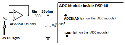
For stable & low impedance signal, i used OPA350 opamp, Resister Rin=33ohm, Capacitor Cin=20PF as per the reference guide "Analog Interface With 28xx
DSCs SPRAAP6.PDF". Then fed this stable & low impedance signal across ADC module of [ADCINA0 & GND] pins and starting the operation of Debugging & Run. But in [ADCRESULT0] register bit printing/calculating random digital value, which is not equivalent to analog input value.

What should i do to generate appropriate digital value?
Am i missing any steps to configure ADC?


Here i'm inserting hardware configuration:

Here i'm including software configuration:
void init_adc(void)
{

    AdcRegs.ADCTRL3.bit.ADCCLKPS = 2;       // ADC Clock Pre scaler (i.e 12.5MHz)
    AdcRegs.ADCTRL3.bit.SMODE_SEL = 0;      // Sequential model

    AdcRegs.ADCMAXCONV.all = 0;             // 1 Conv's on SEQ
    AdcRegs.ADCCHSELSEQ1.bit.CONV00 = 0;    // Setup ADCINA0 as 1st SEQ Conv.

    AdcRegs.ADCTRL1.bit.SEQ_CASC = 1;	    // Cascaded Sequencer Mode
    AdcRegs.ADCTRL1.bit.SEQ_OVRD = 0;       // disable SEQ overriding mode
    AdcRegs.ADCTRL1.bit.CONT_RUN = 1;       // Continuous Run mode
    AdcRegs.ADCTRL1.bit.CPS = 0;            // divide by 1 
    AdcRegs.ADCTRL1.bit.ACQ_PS = 7;	    // S/H=(1+ACQ_PS)*(time of ADCCLK)
    AdcRegs.ADCTRL1.bit.SUSMOD = 0;	    // Emulation suspend is ignored
    AdcRegs.ADCTRL2.bit.RST_SEQ1 = 0;	    // No action

    AdcRegs.ADCTRL2.bit.EPWM_SOCA_SEQ1 = 1; // SEQ1 start from ePWM_SOCA trigger
    AdcRegs.ADCTRL2.bit.INT_ENA_SEQ1 = 1;   // Enable SEQ1 interrupt request to CPU
    AdcRegs.ADCTRL2.bit.INT_MOD_SEQ1 = 0;   // Interrupt after every end of sequence

}

__interrupt void adc_isr(void)
{
	unsigned int  t;
        unsigned int V[200];
for(t=0;t<10;t++) { V[t] = AdcRegs.ADCRESULT0; // Stores Digital value printf("Digital Voltage: V[t]= %u \n", V[t]); } AdcRegs.ADCST.bit.INT_SEQ1_CLR = 1; // Clear INT SEQ1 bit AdcRegs.ADCTRL2.bit.INT_ENA_SEQ1 = 0; // Disable SEQ1 interrupt PieCtrlRegs.PIEACK.all = PIEACK_GROUP1; // Acknowledge interrupt to PIE return; }

  • Hi Asim,

    First of all to verify your code, does your ADC respond to GND and 3.3V signal as 0 and 4095 digital values respectively?


    Regards,

    Gautam

  • Hello Gautam,
    Yes i verified & not produced correct digital value.

  • Check the ADC sample code here: http://www.ti.com/tool/sprc191
    Do the basic check first.

    Regards,
    Gautam
  • Hello Devin Cottier,
    i need your help.
  • Hi Asim,

    The external hardware looks good. Have you confirmed that the input voltage is indeed making it to the ADC input pin, and that you have selected the correct pin?

    As far as the software, I don't really understand why this operation is done in a loop:

    V[t] = AdcRegs.ADCRESULT0;

    Each ISR will only produce 1 new ADC reading. Repeated reads of ADCRESULT0 shouldn't produce new results until the next ePWM trigger. I think what you want instead is a global array to hold the results, and add 1 result to this array each ISR.
  • Hello Devin,
    ======================================================
    # yes, i have selected correct pin ADCINA0.
    # here i have used an array inside loop to hold the result.
    ======================================================

    ADC Digital Value not correct... ???
  • What result are you getting, and what result do you expect? It looks like you should expect (2.0/3.0)*4096 = 2731?

    I think you should also expect every element of V[] to be identical, since you are copying the same value multiple times.
  • Hello Devin,

    I'm following this way (2/3)*4096=2731, but not coming.

    I'm facing a lots of trouble to doing this A/D & here not a single person acquainted with this to providing me some input.

    So please go through my HW as well as SW logic and give input to it.

    4188.ADCVoltageMeasuring.c
    #include "stdio.h"
    #include "stdlib.h"
    #include "DSP280x_Device.h"
    #include "DSP280x_Examples.h"
    
    // Prototype
    void init_system(void);
    void init_epwm1(void);
    void init_adc(void);
    void adc_isr(void);
    
    // Global Variable
     unsigned int V[200];
    
    void main(void)
    {
    	init_system();
    	adc_isr();
    }


    void init_system(void)
    {
    //Step1: Initialize System Control Peripheral Clock:
     		EALLOW;
    		SysCtrlRegs.WDKEY = 0x0055;
    	    SysCtrlRegs.WDKEY = 0x00AA;
    	    SysCtrlRegs.PLLSTS.bit.MCLKSTS = 0;			// Normal condition (Device not in limp mode) (missing OSCCLK clock not been detected)
    //	    SysCtrlRegs.PLLSTS.bit.CLKINDIV = 0;		// CLKIN divide by 2 is enabled
    	    SysCtrlRegs.PLLSTS.bit.MCLKOFF = 1;			// Oscillator fail-detect logic is disabled (PLL not issue limp-mode clock)
    	    SysCtrlRegs.PLLSTS.bit.PLLLOCKS = 0;		// PLL is lock & CPU is clocked by OSCCLK/2
    	    SysCtrlRegs.HISPCP.bit.HSPCLK = 1;			// HSPCLK=SYSCLKOUT/2 (i.e 100/2=50MHz)
    	    SysCtrlRegs.LOSPCP.bit.LSPCLK = 0;			// LSPCLK=SYSCLKOUT
    
    	    SysCtrlRegs.PCLKCR0.bit.TBCLKSYNC = 1;		// Enable clock for all Peripheral
    	    SysCtrlRegs.PCLKCR0.bit.ADCENCLK = 1;		// Enable clock for ADC
    	    SysCtrlRegs.PCLKCR1.bit.EPWM1ENCLK = 1;		// Enable clock for ePWM1
    	    EDIS;
    //Step2: Initialize ECap GPIO Pins:
    	    EALLOW;
    //		GpioCtrlRegs.GPAPUD.bit.GPIO0 = 0;   // Enable pull up on GPIO0
    //        	GpioCtrlRegs.GPADIR.bit.GPIO0 = 1;   // GPIO0 = output
    //		GpioDataRegs.GPASET.bit.GPIO0 = 1;   // Load output latch
    		GpioCtrlRegs.GPAMUX1.bit.GPIO0 = 1;
    	    EDIS;
    
    //Step3: Clear all interrupts and initialize PIE vector table:
    		IER = 0x0000;						// Disable CPU interrupts
    		IFR = 0x0000;						// clear all CPU interrupt flags
    		EALLOW;
    		PieVectTable.ADCINT = &adc_isr;		// initialize PIE Vector Table of ADC1
    		EDIS;
    //Step4: Initialize all the Device Peripherals:
    		init_adc();
    		init_epwm1();
    
    //Step5: User specific code, enable interrupts:
    		// Initialize PIE Control Register:
    	    PieCtrlRegs.PIECTRL.bit.ENPIE = 1;	// Enable PIE (peripheral interrupt expansion)
    		PieCtrlRegs.PIEIER1.bit.INTx6 = 1;	// Enable Interrupt ADCINT
    
    	    IER |= M_INT1; // Enable CPU Interrupt 1
    	    EINT;			// Enable Global interrupt INTM
    	    ERTM;			// Enable Global real time interrupt DBGM
    }
    
    
    void init_epwm1(void)
    {
    	EPwm1Regs.TBPRD = 1000;						// 50KHz
    	    EPwm1Regs.TBCTL.bit.FREE_SOFT = 2;      // free run at emul break
    	    EPwm1Regs.TBCTL.bit.CTRMODE = 2;        // count up-down mode
    	    EPwm1Regs.TBCTL.bit.PHSEN = 0;          // disable phase in
    	    EPwm1Regs.TBCTL.bit.PRDLD = 0;          // reload on counter = 0
    	    EPwm1Regs.TBCTL.bit.SWFSYNC = 0;        // no sw force sync out
    	    EPwm1Regs.TBCTL.bit.SYNCOSEL = 3;       // disable SYNCOUT
    	    EPwm1Regs.TBCTL.bit.HSPCLKDIV = 0;      // HSPCLKDIV = 1
    	    EPwm1Regs.TBCTL.bit.CLKDIV = 0;         // CLKDIV = 1
    	    EPwm1Regs.TBCTL.bit.PHSDIR = 0;         // don't care
    	EPwm1Regs.CMPCTL.bit.SHDWAMODE = CC_SHADOW;
    	EPwm1Regs.CMPCTL.bit.LOADAMODE = CC_CTR_ZERO;
    	EPwm1Regs.CMPA.half.CMPA = 500;
    	EPwm1Regs.AQCTLA.bit.CAU = AQ_SET;
    	EPwm1Regs.AQCTLA.bit.CAD = AQ_CLEAR;
    
    	EPwm1Regs.ETPS.bit.SOCAPRD = 1;         // Generate SOCA pulse on 1st event
    	EPwm1Regs.ETSEL.bit.SOCAEN = 1;         // Enable EPWMAxSOCA pulse
    	EPwm1Regs.ETSEL.bit.SOCASEL = 2;        // Select SOC on PRD event
    
    }
    
    
    void init_adc(void)
    {
    	AdcRegs.ADCTRL2.bit.EPWM_SOCA_SEQ1 = 1; // SEQ1 start from ePWM_SOCA trigger
        AdcRegs.ADCTRL3.bit.ADCCLKPS = 2;      // i.e 4; ADC Clock Pre-scaler (i.e 12.5MHz)
        AdcRegs.ADCTRL3.bit.SMODE_SEL = 0;      // Sequential model
        AdcRegs.ADCREFSEL.bit.REF_SEL = 0;
    
        AdcRegs.ADCMAXCONV.all = 0;             // 1 Conv's on SEQ
        AdcRegs.ADCCHSELSEQ1.bit.CONV00 = 0;    // Setup ADCINA0 as 1st SEQ Conv.
    
    	AdcRegs.ADCTRL1.bit.SEQ_CASC = 1;		// Cascaded Sequencer Mode
        AdcRegs.ADCTRL1.bit.SEQ_OVRD = 0;       // disable SEQ overriding mode
        AdcRegs.ADCTRL1.bit.CONT_RUN = 1;       // Continuous Run mode
        AdcRegs.ADCTRL1.bit.CPS = 0;            // divide by 1 (i.e ADCCLK=12.5mhz=80ns)
    	AdcRegs.ADCTRL1.bit.ACQ_PS = 7;	     // S/H=(1+ACQ_PS)*(time of ADCCLK)
    
    
        AdcRegs.ADCTRL2.bit.INT_ENA_SEQ1 = 1;   // Enable SEQ1 interrupt request to CPU
        AdcRegs.ADCTRL2.bit.INT_MOD_SEQ1 = 0;   // Interrupt after every end of sequence
    
    }
    
    void adc_isr(void)
    {
    	unsigned int  t;
    	for(t=0;t<10;t++)
        	{
               V[t] = AdcRegs.ADCRESULT0;                   // Stores Digital value
          	   printf("Digital Voltage: V[t]= %u \n", V[t]);
        	}
    
        AdcRegs.ADCST.bit.INT_SEQ1_CLR = 1;                // Clear INT SEQ1 bit
        AdcRegs.ADCTRL2.bit.INT_ENA_SEQ1 = 0;               // Disable SEQ1 interrupt
        PieCtrlRegs.PIEACK.all = PIEACK_GROUP1;             // Acknowledge interrupt to PIE
        return;
    }


  • Hi Asim,

    One debug strategy would be to check all the device clocks. First check the PLL settings, and then experimentally verify that the pll settings and SYSCLK is as expected by enabling XCLKOUT and measuring with a scope or counter.

    Once you are sure on the SYSCLK, you may want to make a table of all the dividers for the peripheral clocks and then ADCCLK to ensure that the ADC is getting the correct clock frequency. Once you know what all the dividers should be, you can check that they are getting correctly configured by placing a breakpoint after your initializations. At the breakpoint, use the expressions/watch window to verify all the bits are set as intended.

    Since you are using ePWM driven sampling, you may want to try enabling the ePWM output on a pin, and then using a scope to verify that the sampling trigger period is as intended.

    Other than the clock, it is probably a good idea to check the VDDA, VDDIO, and VDD voltages, as well as the ADC REFP and REFM voltages.

    On the software structure side, you may want to run whatever example we provide with F2808 without modification to see if it works. If not, you may want to target your efforts towards HW issues, but if that example works then you can diff it with your software. In ControlSUITE we also have an ADC example for F2833x, which has a similar device architecture and ADC sampling architecture.
  • Devin,
    ADC REFP & REFM pins are on board and i'll check the voltage by connecting a capacitor (Ceramic Capacitor or Electrolyte Capacitor?)
    But how i'll check VDDA, VDDIO, VDD voltage? that pins are not on the board.
  • Hi Asim,

    Is this a custom board? 

    I don't really follow how you will measure REFP and REFM using a capacitor.  There should be a 2.2uF capacitor already on these pins, which you can probe with a DMM.  There should also be a 22kohm resistor on the ADCRESEXT pin.  It may be worth ohming out this pin to ground to ensure the appropriate resistance is present.  

    Sorry, it looks like the supply pin naming on this device is a bit different.  The pins VDDA2, VDDAIO, and VDDIO should all be 3.3V.  The pins VDD1A18, VDD2A18, and VDD should all be 1.8V.  

  • Hello Devin,

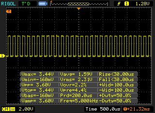
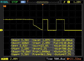
    One thing i'm confusion that PWM pulse always a square wave type & help to perform multiple conversion in ADC, but after Event Trigger (ET) module enabled for EPWM_SOCA_SEQ1, the PWM pulse was changed. Here's two Oscilloscope snapshot (i): Before Event Trigger Module Enable (ii): After Event Trigger Module Enable

    I'm in confusion, Why this's happening?

    If PWM pulse will differ (not a PWM pulse) then ADC may not receives Start-of-Conversion (SOC) request and it can not perform multiple conversions automatically & ADCRESULT digital value not correct?

    (i): Before Event Trigger Module Enable (ET not enable)

    (ii): After Event Trigger Module Enable (ET enable)

  • i have solved the above unwanted PWM pulse problem after ET module enable.

    Now i'll see why ADC not working correctly.