This thread has been locked.

If you have a related question, please click the "Ask a related question" button in the top right corner. The newly created question will be automatically linked to this question.

CCS/LAUNCHXL-F28377S: ADC_SAMPLING_FREQ

Expert 1985 points

Part Number: LAUNCHXL-F28377S

Tool/software: Code Composer Studio

Hi,

I have a question about “2837x_rfft_adc_rt”:

I need to increase my sample rate analog to digital from 100ksps to  500 Ksps,

changing the following parameter in the "example_setup.h" is enough?

#define ADC_SAMPLING_FREQ    100000.0L

or other changes in the project is necessary.

Thank you for your help.

Best regards,

Amin

  • Hi Amin,

    I'm writing to let you know that a C2000 team member has been assigned to this post and should be answering shortly.

    Sean
  • Amin,

    It looks like ADC_SAMPLING_FREQ only adjusts the calculations in main(). It does not affect the code that configures the ePWM in examples_setup.c to actually trigger conversions at a faster rate.

    Whitney
  • Hi Whitney,

    Thank you for your reply. How do I change it to 500ksps?

    Best regards,

    Amin

  • The EPWM1_PERIOD and EPWM1_DUTY_CYCLE macros in example_setup.h control the ePWM that triggers conversions. If you divide them both by five that should do it.

    Whitney
  • Dear Whitney,

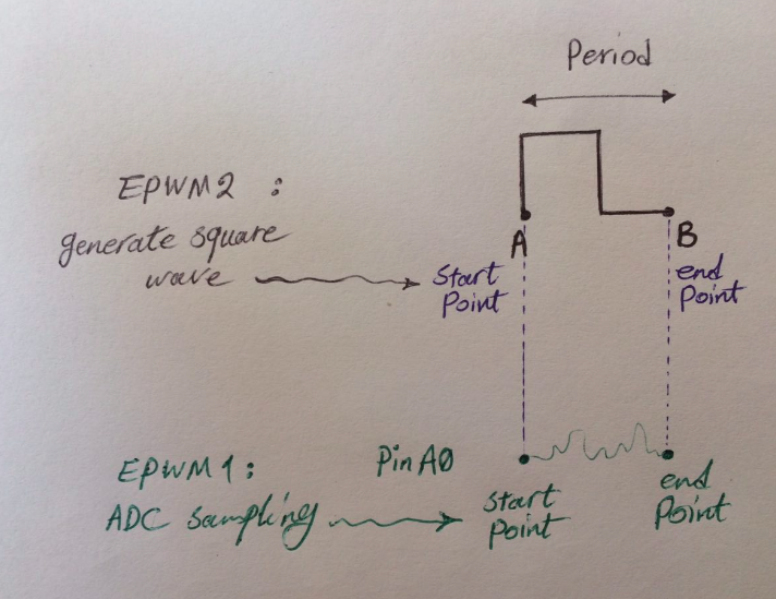
    In this project(2837x_rfft_adc_rt) there is a square wave generator, I want to control the start and stop point of each pulses and sampling the analog signal in other ADC channel at the same time.

    How can I generate a certain number of square wave, for example 1 square wave? I need to have the “start” and “end” points of each square wave in the project and run ADC pin_A0 from start point to end point of each square wave.

    In other words, If we assume “A” is the start point of each pulse period, and the end point of each period is point “B”,  then: 

    start point of ADC= at the beginning of square wave(point A)

    end point of ADC= at the end point of square wave(point B)

    How do I synchronize the ADC channel and Square wave generator?

    Thank you and best regards,

    Amin

  • Hi Amin,

    The example you're using already has the PWMs configured to start their clocks at the same time. That's what's happening in FPU_startEPWM() where the TBCLKSYNC bit is being set. Then if you've configured the two PWM modules to have the same period and dividers (see the TBPRD and TBCTL registers) they should have the same end points too. Have you tried that?

    Whitney

  • The frequency of ADC and the PWM is not equal.
    PWM freq. = 200Hz
    ADC sampling freq. = 500ksps
    Please show me in the project. Thank you for your help.
    Amin
  • In examples_setup.h, what values are the #defines for period and duty cycle?

    Also, make sure you have _LAUNCHXL_F28377S in your predefined symbols in your projects' compiler settings. You need to do that to make sure InitSysCtrl() is configuring the system clock to run at the expected 200MHz.

    Whitney
  • In examples_setup.h :

    1
    2
    3
    4
    5
    6
    7
    8
    9
    10
    11
    #define CPU_FRQ_200MHZ          1
    #define ADC_SAMPLING_FREQ       100000.0L
    #define EPWM_CLK                100000000UL // EPWM_CLK starts off SYSCLK/2
    #define EPWM_CLKDIV             1           // TBCLK = SYSCLK/(2*2)
    #define EPWM_HSPCLKDIV          4           //       = SYSCLK/(2*2*8) or EPWM_CLK/(2*8)
    // desired freq 100KHz
    #define EPWM1_PERIOD            EPWM_CLK/(2*8*100000UL)
    #define EPWM1_DUTY_CYCLE        EPWM1_PERIOD/2UL
    // desired freq 10KHz
    #define EPWM2_PERIOD            (EPWM_CLK)/(2*8*10000UL)
    #define EPWM2_DUTY_CYCLE        EPWM2_PERIOD/2UL
  • This code looks like it's setting up the PWMs to run at 100kHz. Where are you seeing 200Hz? Is that what you see when you look at the PWM signals on an oscilloscope?

    Whitney
  • I see 99.174KHz with oscilloscope.
  • Okay, that is what I would expect given the code you showed me. So if you wanted to trigger an ADC conversion at a rate of 500kHz, you would just need to change 100k to 500k in the #defines for the period, right?

    #define EPWM1_PERIOD EPWM_CLK/(2*8*500000UL)

    Or am I misunderstanding what you're trying to do?

    Whitney
  • When I change this line:
    #define EPWM1_PERIOD EPWM_CLK/(2*8*500000UL)
    ADC sampling freq=500ksps and it works good.
    but for pwm generator, when
    #define EPWM2_PERIOD EPWM_CLK/(2*8*200UL)
    , signal generator not works(200Hz signal)
  • I have a voltage control oscillator with single input (connect to pwm(200Hz) of launchpad-f28377s), and single output(connect to ADC pin A0 with 500ksps). I need to start pwm and ADC from start point to end point of each pulse.
  • 200 Hz pulse production was created.
    Operates correctly.
    My question is how to set start and stop of each pulse wit ADC(start and stop of sampling)?
    Amin
  • following code: result(500ksps ADC and 200Hz pwm)

    #define CPU_FRQ_200MHZ 1
    #define ADC_SAMPLING_FREQ 500000.0L
    #define EPWM_CLK 100000000UL // EPWM_CLK starts off SYSCLK/2
    #define EPWM_CLKDIV 1 // TBCLK = SYSCLK/(2*2)
    #define EPWM_HSPCLKDIV 4 // = SYSCLK/(2*2*8) or EPWM_CLK/(2*8)
    // desired freq 100KHz
    #define EPWM1_PERIOD       EPWM_CLK/(2*8*500000UL)
    #define EPWM1_DUTY_CYCLE   EPWM1_PERIOD/2UL
    // desired freq 10KHz
    #define EPWM2_PERIOD      (EPWM_CLK)/(2*8*200UL)
    #define EPWM2_DUTY_CYCLE   EPWM2_PERIOD/2UL


    Amin

  • The original 2837x_rfft_adc_rt example has configured the ADC's SOC0 to be triggered by ePWM1 SOCA (ADCSOC0CTL.TRIGSEL = 5). It also configured the ePWM to generate the SOCA signal when TBCTR = CMPA (ETSEL.SOCASEL = 4). That basically means the conversion starts on the rising edge of the ePWM1A signal.

    I'm not sure what you mean by "stop of sampling." Once the conversion is started, the sample and hold time is determined by ADCSOC0CTL.ACQPS which the example code has configured to 15 SYSCLK cycles. I believe this is the minimum required sampling time for a 12-bit conversion on the F28377S. It then takes a number of cycles to for the result to be latched into the result registers and for the ADC interrupt to be generated. You can look at the ADC Timings section of the TRM if you want the details:

    www.ti.com/.../spruhm8

    The end of the actual sampling window isn't determined by the ePWM. Perhaps I'm not fully understanding what you're trying to do...?

    Whitney
  • Whitney,

    Thank you very much for your help.

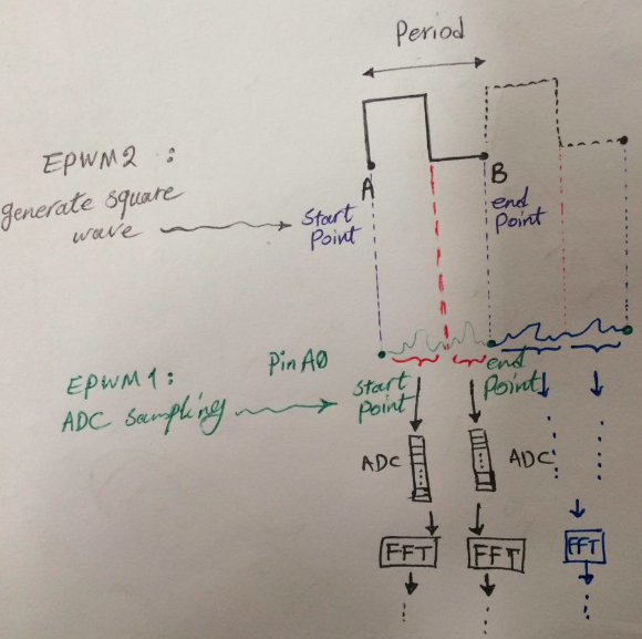
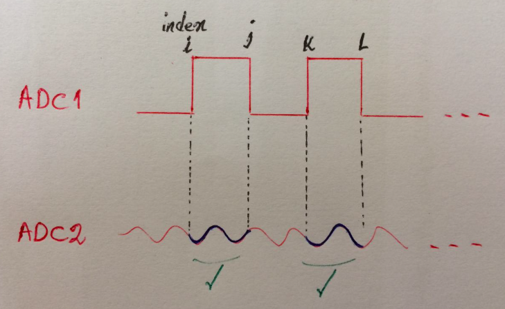
    My goal is ADC sampling at the rising edge to rising edge of the next pulse.

    Because I need to have the samples(ADC pin) corresponding to each pulse(generated by PWM),

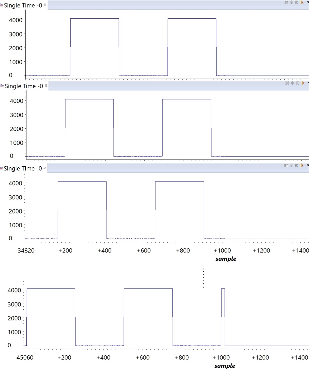
    As it is seen in Fig., Sampling begins at the beginning of each pulse to the beginning of the next pulse(this will not be done for all pulses), and then split the samples on the falling edge of the pulse.

    I'm not saying stop function(said before post "the end point"), my goal is just find the location of the rising edge of each pulses.

    Thanks and Best regards,

    Amin

  • Okay, I think I understand. You could configure ePWM2 to trigger an interrupt on the a CMPA event (which is the rising edge in your configuration). The epwm_up_aq example in controlSUITE demonstrates how to configure a PWM interrupt if you need an example. Will that do what you need?

    Whitney

  • Hi Whitney,

    In this project we have a change in pulse duty cycle, but I do not need this change. I was reduced the code to a pulse generator(ePWM2).

    //###########################################################################
    //
    // FILE:   epwm_up_aq_cpu01.c
    //
    // TITLE:  Action Qualifier Module - Using up count.
    //
    //! \addtogroup cpu01_example_list
    //! <h1> EPWM Action Qualifier (epwm_up_aq)</h1>
    //!
    //! This example configures ePWM1, ePWM2, ePWM3 to produce an
    //! waveform with independent modulation on EPWMxA and
    //! EPWMxB.
    //!
    //! The compare values CMPA and CMPB are modified within the ePWM's ISR.
    //!
    //! The TB counter is in up count mode for this example.
    //!
    //! View the EPWM1A/B(PA0_GPIO0 & PA1_GPIO1), EPWM2A/B(PA2_GPIO2 & PA3_GPIO3)
    //! and EPWM3A/B(PA4_GPIO4 & PA5_GPIO5) waveforms via an oscilloscope.
    //!
    //
    //###########################################################################
    // $TI Release: F2837xS Support Library v210 $
    // $Release Date: Tue Nov  1 15:35:23 CDT 2016 $
    // $Copyright: Copyright (C) 2014-2016 Texas Instruments Incorporated -
    //             http://www.ti.com/ ALL RIGHTS RESERVED $
    //###########################################################################
    
    //
    // Included Files
    //
    #include "F28x_Project.h"
    
    //
    // Defines
    //
    
    #define EPWM2_TIMER_TBPRD  2000  // Period register ////////////2000
    #define EPWM2_MAX_CMPA     1950 //1950
    #define EPWM2_MIN_CMPA       50
    #define EPWM2_MAX_CMPB     1950 //1950
    #define EPWM2_MIN_CMPB       50
    
    
    #define EPWM_CMP_UP           1
    #define EPWM_CMP_DOWN         0
    
    //
    // Globals
    //
    typedef struct
    {
        volatile struct EPWM_REGS *EPwmRegHandle;
        Uint16 EPwm_CMPA_Direction;
        Uint16 EPwm_CMPB_Direction;
        Uint16 EPwmTimerIntCount;
        Uint16 EPwmMaxCMPA;
        Uint16 EPwmMinCMPA;
        Uint16 EPwmMaxCMPB;
        Uint16 EPwmMinCMPB;
    }EPWM_INFO;
    
    EPWM_INFO epwm2_info;
    
    
    //
    //  Function Prototypes
    //
    
    void InitEPwm2Example(void);
    
    __interrupt void epwm2_isr(void);
    
    void update_compare(EPWM_INFO*);
    
    //
    // Main
    //
    void main(void)
    {
    //
    // Step 1. Initialize System Control:
    // PLL, WatchDog, enable Peripheral Clocks
    // This example function is found in the F2837xS_SysCtrl.c file.
    //
        InitSysCtrl();
    
    //
    // Step 2. Initialize GPIO:
    // This example function is found in the F2837xS_Gpio.c file and
    // illustrates how to set the GPIO to it's default state.
    //
    //    InitGpio();
    
    //
    // Enable PWM2
    //
    
        CpuSysRegs.PCLKCR2.bit.EPWM2=1;
    //
    // For this case just init GPIO pins for ePWM1, ePWM2, ePWM3
    // These functions are in the F2837xS_EPwm.c file
    //
        InitEPwm2Gpio();
    
    //
    // Step 3. Clear all interrupts and initialize PIE vector table:
    // Disable CPU interrupts
    //
        DINT;
    
    //
    // Initialize the PIE control registers to their default state.
    // The default state is all PIE interrupts disabled and flags
    // are cleared.
    // This function is found in the F2837xS_PieCtrl.c file.
    //
        InitPieCtrl();
    
    //
    // Disable CPU interrupts and clear all CPU interrupt flags:
    //
        IER = 0x0000;
        IFR = 0x0000;
    
    //
    // Initialize the PIE vector table with pointers to the shell Interrupt
    // Service Routines (ISR).
    // This will populate the entire table, even if the interrupt
    // is not used in this example.  This is useful for debug purposes.
    // The shell ISR routines are found in F2837xS_DefaultIsr.c.
    // This function is found in F2837xS_PieVect.c.
    //
        InitPieVectTable();
    
    //
    // Interrupts that are used in this example are re-mapped to
    // ISR functions found within this file.
    //
        EALLOW; // This is needed to write to EALLOW protected registers
        PieVectTable.EPWM2_INT = &epwm2_isr;
        EDIS;   // This is needed to disable write to EALLOW protected registers
    
    //
    // For this example, only initialize the ePWM
    //
        EALLOW;
        CpuSysRegs.PCLKCR0.bit.TBCLKSYNC = 0;
        EDIS;
    
        InitEPwm2Example();
    
        EALLOW;
        CpuSysRegs.PCLKCR0.bit.TBCLKSYNC = 1;
        EDIS;
    
    //
    // Step 4. User specific code, enable interrupts:
    //
    // Enable CPU INT3 which is connected to EPWM1-3 INT:
    //
        IER |= M_INT3;
    
    //
    // Enable EPWM INTn in the PIE: Group 3 interrupt 1-3
    //
        PieCtrlRegs.PIEIER3.bit.INTx2 = 1;
    
    //
    // Enable global Interrupts and higher priority real-time debug events:
    //
        EINT;  // Enable Global interrupt INTM
        ERTM;  // Enable Global realtime interrupt DBGM
    
    //
    // Step 5. IDLE loop. Just sit and loop forever (optional):
    //
        for(;;)
        {
            asm ("  NOP");
        }
    }
    
    
    //
    // epwm2_isr - EPWM2 ISR to update compare values
    //
    __interrupt void epwm2_isr(void)
    {
        //
        // Update the CMPA and CMPB values
        //
        update_compare(&epwm2_info);
    
        //
        // Clear INT flag for this timer
        //
        EPwm2Regs.ETCLR.bit.INT = 1;
    
        //
        // Acknowledge this interrupt to receive more interrupts from group 3
        //
        PieCtrlRegs.PIEACK.all = PIEACK_GROUP3;
    }
    
    //
    // InitEPwm2Example - Initialize EPWM2 values
    //
    void InitEPwm2Example()
    {
       //
       // Setup TBCLK
       //
       EPwm2Regs.TBCTL.bit.CTRMODE = TB_COUNT_UP; // Count up
       EPwm2Regs.TBPRD = EPWM2_TIMER_TBPRD;       // Set timer period
       EPwm2Regs.TBCTL.bit.PHSEN = TB_DISABLE;    // Disable phase loading
       EPwm2Regs.TBPHS.bit.TBPHS = 0x0000;        // Phase is 0
       EPwm2Regs.TBCTR = 0x0000;                  // Clear counter
       EPwm2Regs.TBCTL.bit.HSPCLKDIV = TB_DIV2;   // Clock ratio to SYSCLKOUT
       EPwm2Regs.TBCTL.bit.CLKDIV = TB_DIV2;
    
       //
       // Setup shadow register load on ZERO
       //
       EPwm2Regs.CMPCTL.bit.SHDWAMODE = CC_SHADOW;
       EPwm2Regs.CMPCTL.bit.SHDWBMODE = CC_SHADOW;
       EPwm2Regs.CMPCTL.bit.LOADAMODE = CC_CTR_ZERO;
       EPwm2Regs.CMPCTL.bit.LOADBMODE = CC_CTR_ZERO;
    
       //
       // Set Compare values
       //
       EPwm2Regs.CMPA.bit.CMPA = EPWM2_MIN_CMPA;      // Set compare A value
       EPwm2Regs.CMPB.bit.CMPB = EPWM2_MAX_CMPB;      // Set Compare B value
    
       //
       // Set actions
       //
       EPwm2Regs.AQCTLA.bit.PRD = AQ_CLEAR;            // Clear PWM2A on Period
       EPwm2Regs.AQCTLA.bit.CAU = AQ_SET;              // Set PWM2A on event A,
                                                       // up count
    
       EPwm2Regs.AQCTLB.bit.PRD = AQ_CLEAR;            // Clear PWM2B on Period
       EPwm2Regs.AQCTLB.bit.CBU = AQ_SET;              // Set PWM2B on event B,
                                                       // up count
    
       //
       // Interrupt where we will change the Compare Values
       //
       EPwm2Regs.ETSEL.bit.INTSEL = ET_CTR_ZERO;       // Select INT on Zero event
       EPwm2Regs.ETSEL.bit.INTEN = 1;                  // Enable INT
       EPwm2Regs.ETPS.bit.INTPRD = ET_3RD;             // Generate INT on 3rd event
    
       //
       // Information this example uses to keep track
       // of the direction the CMPA/CMPB values are
       // moving, the min and max allowed values and
       // a pointer to the correct ePWM registers
       //
       epwm2_info.EPwm_CMPA_Direction = EPWM_CMP_UP;   // Start by increasing CMPA
       epwm2_info.EPwm_CMPB_Direction = EPWM_CMP_DOWN; // and decreasing CMPB
       epwm2_info.EPwmTimerIntCount = 0;               // Zero the interrupt
                                                       // counter
       epwm2_info.EPwmRegHandle = &EPwm2Regs;          // Set the pointer to the
                                                       // ePWM module
       epwm2_info.EPwmMaxCMPA = EPWM2_MAX_CMPA;        // Setup min/max
                                                       // CMPA/CMPB values
       epwm2_info.EPwmMinCMPA = EPWM2_MIN_CMPA;
       epwm2_info.EPwmMaxCMPB = EPWM2_MAX_CMPB;
       epwm2_info.EPwmMinCMPB = EPWM2_MIN_CMPB;
    }
    
    
    //
    // update_compare - Update the compare values for the specified EPWM
    //
    void update_compare(EPWM_INFO *epwm_info)
    {
       //
       // Every 10'th interrupt, change the CMPA/CMPB values
       //
       if(epwm_info->EPwmTimerIntCount == 1)  ///////////////////////10
       {
           epwm_info->EPwmTimerIntCount = 0;
    
           //
           // If we were increasing CMPA, check to see if
           // we reached the max value.  If not, increase CMPA
           // else, change directions and decrease CMPA
           //
           if(epwm_info->EPwm_CMPA_Direction == EPWM_CMP_UP)
           {
               if(epwm_info->EPwmRegHandle->CMPA.bit.CMPA < epwm_info->EPwmMaxCMPA)
               {
                  epwm_info->EPwmRegHandle->CMPA.bit.CMPA++;
               }
               else
               {
                  epwm_info->EPwm_CMPA_Direction = EPWM_CMP_DOWN;
                  epwm_info->EPwmRegHandle->CMPA.bit.CMPA--;
               }
           }
    
           //
           // If we were decreasing CMPA, check to see if
           // we reached the min value.  If not, decrease CMPA
           // else, change directions and increase CMPA
           //
           else
           {
               if(epwm_info->EPwmRegHandle->CMPA.bit.CMPA == epwm_info->EPwmMinCMPA)
               {
                  epwm_info->EPwm_CMPA_Direction = EPWM_CMP_UP;
                  epwm_info->EPwmRegHandle->CMPA.bit.CMPA++;
               }
               else
               {
                  epwm_info->EPwmRegHandle->CMPA.bit.CMPA--;
               }
           }
    
           //
           // If we were increasing CMPB, check to see if
           // we reached the max value.  If not, increase CMPB
           // else, change directions and decrease CMPB
           //
           if(epwm_info->EPwm_CMPB_Direction == EPWM_CMP_UP)
           {
               if(epwm_info->EPwmRegHandle->CMPB.bit.CMPB < epwm_info->EPwmMaxCMPB)
               {
                  epwm_info->EPwmRegHandle->CMPB.bit.CMPB++;
               }
               else
               {
                  epwm_info->EPwm_CMPB_Direction = EPWM_CMP_DOWN;
                  epwm_info->EPwmRegHandle->CMPB.bit.CMPB--;
               }
           }
    
           //
           // If we were decreasing CMPB, check to see if
           // we reached the min value.  If not, decrease CMPB
           // else, change directions and increase CMPB
           //
           else
           {
               if(epwm_info->EPwmRegHandle->CMPB.bit.CMPB ==
                  epwm_info->EPwmMinCMPB)
               {
                  epwm_info->EPwm_CMPB_Direction = EPWM_CMP_UP;
                  epwm_info->EPwmRegHandle->CMPB.bit.CMPB++;
               }
               else
               {
                  epwm_info->EPwmRegHandle->CMPB.bit.CMPB--;
               }
           }
       }
       else
       {
          epwm_info->EPwmTimerIntCount++;
       }
    
       return;
    }
    
    //
    // End of file
    //
    

    Thank you.

    Regards,

    Amin

  • Amin,

    Yes, I understand that the example on whole is not relevant to what you're trying to do, but I thought the few lines that configure ETSEL and ETPS might help you implement the interrupt in your own project if that's what you decided you needed.

    Whitney

  • Whitney
    You can suggest another way?
    Amin
  • Another way to detect the edge? Will generating a ePWM interrupt (or poll the interrupt flag) not work for you?

    Whitney
  • Yes, please explain in more detail.
    Amin
  • One way is to start ADC sampling and pulse generation simultaneously.
    If I can restart pulse generator and ADC (ePWM1 and ePWM2) my problem will be solved (Both ePWM1 and ePWM2 start to work at the rising edge and synchronized).
    Thank you for your help.
    Amin
  • Okay, perhaps the issue is that currently that the rising edge is at CMPA (which is different for both PWMs).

    // Clear PWM1A on Zero
    EPwm1Regs.AQCTLA.bit.CAU = AQ_SET;
    EPwm1Regs.AQCTLA.bit.PRD = AQ_CLEAR;
    // Clear PWM2A on Zero
    EPwm2Regs.AQCTLA.bit.CAU = AQ_SET;
    EPwm2Regs.AQCTLA.bit.PRD = AQ_CLEAR;

    So maybe you want to change the above code so that the rising edge is at zero?

    EPwm1Regs.AQCTLA.bit.ZRO = AQ_SET;
    EPwm1Regs.AQCTLA.bit.CAU = AQ_CLEAR;
    EPwm2Regs.AQCTLA.bit.ZRO = AQ_SET;
    EPwm2Regs.AQCTLA.bit.CAU = AQ_CLEAR;

    Also, even if they start in sync, they're going to get out of sync. You're currently setting the ePWM1 period to 12 and the ePWM2 period to 31250 which isn't divisible by 12. So you can either reconfigure the ePWM dividers until you're able to get two PRD values that can stay synchronized, or you'll have to resynchronize them by clearing TBCLKSYNC, clearing the TBCTR, and setting TBCLKSYNC.

    I apologize if I'm repeatedly misunderstanding what you're saying the issue is

    Whitney
  • Hi Whitney,

    With your suggestion, signal is not produced in the particular edge and it is variable.

    An example for clarification:

    Assume that we have two channels simultaneous ADC,

    ADC1 connected to a pulse generator with fix frequency and duty cycle(the pwm channel connected to a device to generate signal ’S’).

    ADC2 connected to an arbitrary signal ’S’.

    Then we have two vectors and we need find the following index(i,j,k,l, …) to separate the signal on the second channel(this method is complex).

    Now, instead of two channels simultaneous ADC, I have a PWM generator (ePWM2) and an ADC channel(ePWM1).

    If I know the pulse is generated at the rising edge and ADC start to sampling at the same time,

    since the pulse frequency is fixed, I can separate the samples in a fixed index.

    I need to always generate pulses in a special way(rising or falling edge) and start sampling at this time.

    Thanks and best regards,

    Amin

  • Do you have any waveform captures that show what is wrong with your current configuration? I think I have a general understanding of what you're trying to do but it's not clear to me which pieces you're having trouble implementing.

    Thank you for your patience,
    Whitney
  • Hi Whitney,

    The main function is as follows:

    Breakpoint placed in the while(1) loop,

    Please see this function:  __interrupt void adcaIsr()

    //#############################################################################
    //! \file /2837x_RFFT_ADC/main.c
    //!
    //! \brief  Demo code for the 512 pt real-time RFFT with the input from the ADC
    //! \author Vishal Coelho (Modified the original)
    //! \date   03/26/2015   
    //! 
    //! This program shows how to compute a real FFT with 12-bit real-time ADC 
    //! input and associated spectrum magnitude, phase. EPWM1 and 2 are setup 
    //! such that EPWM2 outputs a square wave at a frequency 10 times slower 
    //! than EPWM1; EPWM1 serves as the sample clock to the ADC which will 
    //! sample EPWM2A (pin 53) through channel A0 (pin 09) and then run the FFT. 
    //! The real time FFT is computed frame-by-frame. Once a entire frame is 
    //! filled up in the ADC ISR, it sets off a flag to start the FFT. The 
    //! flag is reset once the computation is complete
    //!
    //! \note This example uses the F2837xD controlCARD Rev1.1
    //! \note The input buffer must be aligned to a 2N word boundary, N being the
    //! size of the real FFT. The user may choose to use an alternative routine, 
    //! RFFT_adc_f32u(), if alignment is not possible (or not desired). In that 
    //! case, the section alignment #pragma can be commented.  However, using this 
    //! function will reduce cycle performance of the algorithm.
    //!
    //  Group:             C2000
    //  Target Family:     F2837x
    //
    //#############################################################################
    // $TI Release: C28x Floating Point Unit Library V1.50.00.00 $
    // $Release Date: May 22, 2017 $
    // $Copyright: Copyright (C) 2017 Texas Instruments Incorporated -
    //             http://www.ti.com/ ALL RIGHTS RESERVED $
    //#############################################################################
    
    //*****************************************************************************
    // includes
    //*****************************************************************************
    #include "fpu_rfft.h"            // Main include file
    #include "math.h"
    #include "examples_setup.h"
    
    //!
    //! \addtogroup RFFT_EXAMPLES Real FFT of the ADC Input (Real-Time)
    
    // @{
    //*****************************************************************************
    // defines
    //*****************************************************************************
    #define RFFT_STAGES     9
    #define RFFT_SIZE       (1 << RFFT_STAGES) 
    #define F_PER_SAMPLE    (ADC_SAMPLING_FREQ/(float)RFFT_SIZE)
    #define USE_TEST_INPUT  1 // If not in test mode, be sure to exclude signal.asm
                              // from the build
    #define EPSILON         0.1
    //*****************************************************************************
    // globals
    //*****************************************************************************
    
    #ifdef __cplusplus
    #pragma DATA_SECTION("RFFTdata1")
    #else
    #pragma DATA_SECTION(RFFTin1Buff,"RFFTdata1")
    #endif //__cplusplus
    //! \brief FFT Calculation Buffer
    //! \note The input buffer needs to be aligned to an 2N word boundary
    //! \note If the number of FFT stages is odd, the result of the FFT will
    //! be written to this buffer
    //! \note this buffer takes N 12-bit ADC input, hence its defined as an
    //! unsigned int array, but the FFT algorithm ping-pongs between input/
    //! output buffers each stage, therefore this buffer needs to be able 
    //! to accommodate N floats and should be of size 2*RFFT_SIZE
    uint16_t RFFTin1Buff[2*RFFT_SIZE];
    
    #ifdef __cplusplus
    #pragma DATA_SECTION("RFFTdata2")
    #else
    #pragma DATA_SECTION(RFFTmagBuff,"RFFTdata2")
    #endif //__cplusplus
    //! \brief Magnitude Calculation Buffer
    //!
    float RFFTmagBuff[RFFT_SIZE/2+1];               
    
    #ifdef __cplusplus
    #pragma DATA_SECTION("RFFTdata2")
    #else
    #pragma DATA_SECTION(RFFTmagBuff,"RFFTdata2")
    #endif //__cplusplus
    //! \brief Phase Calculation Buffer
    //!
    float RFFTphaseBuff[RFFT_SIZE/2]; 
    
    #ifdef __cplusplus
    #pragma DATA_SECTION("RFFTdata3")
    #else
    #pragma DATA_SECTION(RFFToutBuff,"RFFTdata3")
    #endif //__cplusplus
    //! \brief FFT Calculation Buffer
    //! \note If the number of FFT stages is even, the result of the FFT will
    //! be written to this buffer
    //!
    float RFFToutBuff[RFFT_SIZE];
    
    #ifdef __cplusplus
    #pragma DATA_SECTION("RFFTdata4")
    #else
    #pragma DATA_SECTION(RFFTF32Coef,"RFFTdata4")
    #endif //__cplusplus
    //! \brief Twiddle Factors
    //!
    float RFFTF32Coef[RFFT_SIZE];
    
    //! \brief RFFT_ADC_F32_STRUCT object
    //!
    RFFT_ADC_F32_STRUCT rfft_adc;
    
    //! \brief Handle to the RFFT_ADC_F32_STRUCT object
    //! 
    RFFT_ADC_F32_STRUCT_Handle hnd_rfft_adc = &rfft_adc;
    
    //! \brief RFFT_F32_STRUCT object
    //!
    RFFT_F32_STRUCT rfft;
    
    //! \brief Handle to the RFFT_F32_STRUCT object
    //!
    RFFT_F32_STRUCT_Handle hnd_rfft = &rfft;
    
    //! \brief Flag to signal the ADC has finished sampling, and storing, 
    //! N points in the FFT input buffer
    //!
    volatile uint16_t flagInputReady = 0;
    
    //! \brief Index into the FFT input buffer
    //!
    volatile uint16_t sampleIndex = 0;
    
    //*****************************************************************************
    // Function Prototypes
    //*****************************************************************************
    __interrupt void adcaIsr();
    //*****************************************************************************
    // function definitions
    //*****************************************************************************
    //!
    //! \brief main routine for the 512-sample RFFT ADC example
    //! \return returns a 1
    //!
    //! This program shows how to compute the real FFT, magnitude and phase of 
    //! data from the 12-bit ADC input. The input buffer must be aligned to a 
    //! 2N word boundary if using RFFT_f32.  
    //! Data section alignment (#pragma ...) is not necessary for RFFT_adc_f32u 
    //! but necessary when running RFFT_adc_f32.  However, using the unaligned 
    //! version will reduce cycle performance of the algorithm.
    //!
    //! The minimum number of stages is 3. When the number of stages is more 
    //! than 9, the quantization error would be significant and not recommended. 
    //! This example will sample an EPWM channel over an ADC channel and run the 
    //! RFFT on a real signal.
    //!
    //! RFFT_F32_STRUCT is a structure defined as:
    //!
    //!    typedef struct {
    //!      float  *InBuf;
    //!      float  *OutBuf;
    //!      float  *CosSinBuf;
    //!      float  *MagBuf;
    //!      float  *PhaseBuf;
    //!      uint16_t FFTSize;
    //!      uint16_t FFTStages;
    //!    } RFFT_F32_STRUCT;
    //! 
    //! RFFT_ADC_F32_STRUCT is defined as:
    //!    typedef struct {
    //!      uint16_t   *InBuf;
    //!      void       *Tail; 
    //!    } RFFT_ADC_F32_STRUCT;
    //!
    //!  ASSUMPTIONS:
    //!
    //! -# OutBuf of RFFT_F32_STRUCT has to be passed to Tail of 
    //!    RFFT_ADC_F32_STRUCT
    //! -# Input signal is stored in Signal.asm
    //! -# FFTSize must be a power of 2 (32, 64, 128, etc)
    //! -# FFTSize must be greater or equal to 32
    //! -# FFTStages must be log2(FFTSize)
    //! -# InBuf, OutBuf, CosSinBuf are FFTSize in length
    //! -# Magnitude buffer is FFTSize/2+1 in length
    //! -# Phase buffer is FFTSize/2 in length
    //!
    //! Watch Variables:
    //!
    //! -# InBuf(RFFT_ADC_F32_STRUCT)    Input buffer
    //! -# InBuf(RFFT_F32_STRUCT)        Not used
    //! -# Tail                          Stored the address of OutBuf
    //! -# OutBuf                        Output buffer
    //! -# CosSinBuf                     Twiddle factor buffer
    //! -# MagBuf                        Magnitude buffer
    //! -# PhaseBuf                      Phase buffer
    //! -# j                             Index of normalized digital frequency component
    //! -# freq                          Real analog frequency of raw signal
    //!
    //! External Connections:
    //! Connect A0 (pin 9) to EPWM2A (pin 53) on the F2837x controlCARD. Refer to the
    //! board schematic for pin positioning.
    //! \note  The ADC will sample a 50% duty cycle 1KHz wave (EPWM2A) at 100KHz
    //! and run the FFT on it. Since the input is a square wave, you will
    //! see the fundamental frequency, 1KHz, at the 5th bin 
    //! (5*fs/N = 5*100K/512 = 976.5) and all its odd harmonics. Since the sampled 
    //! waveform is not an integer multiple of the FFT_SIZE, you will see some 
    //! spectral leakage, a portion of the fundamental will leak into the 6th bin. 
    //! One way to overcome this is to window the input before running the FFT on 
    //! it.
    //!
    int16_t main(void)
    {
        // Locals
        uint16_t i, j;
        float freq = 0.0;
    
    #ifdef FLASH
        EALLOW;
        Flash0EccRegs.ECC_ENABLE.bit.ENABLE = 0;
        memcpy((uint32_t *)&RamfuncsRunStart, (uint32_t *)&RamfuncsLoadStart,
                (uint32_t)&RamfuncsLoadSize );
        FPU_initFlash();
    #endif //FLASH
        
        FPU_initSystemClocks();
        
        FPU_initEpie();
    
        // Setup ADC-A
        FPU_initADCA();
        
        //Setup EPWM1A as the sampling clock, EPWM2A as the signal to be
        //sampled
        FPU_initEPWM(); 
        
        //Map ISR functions
        EALLOW;
        PieVectTable.ADCA1_INT = &adcaIsr; //function for ADCA interrupt 1
        EDIS;
        //Enable global Interrupts and higher priority real-time debug events:
        PieCtrlRegs.PIEIER1.bit.INTx1 = 1; //Enable ADC1INT
        IER |= M_INT1;  //Enable group 1 interrupts
        EINT;           // Enable Global interrupt INTM
        ERTM;           // Enable Global realtime interrupt DBGM
        
        //Start up the EPWMs
        FPU_startEPWM();
        
        //Link the RFFT_ADC_F32_STRUCT to RFFT_F32_STRUCT. Tail pointer 
        //of RFFT_ADC_F32_STRUCT is passed to the OutBuf pointer of 
        //RFFT_F32_STRUCT 
        hnd_rfft_adc->Tail = &(hnd_rfft->OutBuf);
        
        hnd_rfft->FFTSize   = RFFT_SIZE;         //FFT size
        hnd_rfft->FFTStages = RFFT_STAGES;       //FFT stages
    
        hnd_rfft_adc->InBuf = &RFFTin1Buff[0];   //Input buffer (12-bit ADC input)
        hnd_rfft->OutBuf    = &RFFToutBuff[0];   //Output buffer
        hnd_rfft->CosSinBuf = &RFFTF32Coef[0];   //Twiddle factor 
        hnd_rfft->MagBuf    = &RFFTmagBuff[0];   //Magnitude output buffer
        hnd_rfft->PhaseBuf  = &RFFTphaseBuff[0]; //Phase output buffer
        
        RFFT_f32_sincostable(hnd_rfft);          //Calculate twiddle factor
    
        for (i=0; i < RFFT_SIZE; i++){
            RFFToutBuff[i] = 0;                  //Clean up output buffer
        }                                        
                                                 
        for (i=0; i <= RFFT_SIZE/2; i++){        
            RFFTmagBuff[i] = 0;                  //Clean up magnitude buffer
        }                                        
                                                 
        for (i=0; i < RFFT_SIZE/2; i++){         
            RFFTphaseBuff[i] = 0;                //Clean up phase buffer
        } 
        
        while(1){
            while(flagInputReady == 0){}; // Wait on ADC ISR to set the flag 
                                          // before proceeding
            RFFT_adc_f32(hnd_rfft_adc);   // Calculate real FFT (12-bit ADC input)  <----------------------------BreakPoint
            flagInputReady = 0;           // Reset the flag
            
    #ifdef __TMS320C28XX_TMU__ //defined when --tmu_support=tmu0 in the project 
                               // properties
            RFFT_f32_mag_TMU0(hnd_rfft);        //Calculate magnitude
            RFFT_f32_phase_TMU0(hnd_rfft);      //Calculate phase
    #else                                       
            RFFT_f32_mag(hnd_rfft);             //Calculate magnitude
            RFFT_f32_phase(hnd_rfft);           //Calculate phase
    #endif //__TMS320C28XX_TMU__
    
            //Find out the maximum frequency component of signal frequency 
            //component signal. This algorithm is only used for finding frequency 
            //of one component frequency signal; in this example it gives the
            //fundamental frequency of the sampled square wave
            j = 1;
            freq = RFFTmagBuff[1];
            for(i=2;i<RFFT_SIZE/2+1;i++){
            //Looking for the maximum component of frequency spectrum
                if(RFFTmagBuff[i] > freq){
                    j = i;
                    freq = RFFTmagBuff[i];
                }
            }
    
            //Converting normalized digital frequency to real analog frequency
            //f = m * fs/N
            // where m is the bin with the maximum value, fs the sampling
            // frequency and N the number of points in the FFT
            freq = F_PER_SAMPLE * (float)j;     
        }
    
        // Execution never reaches this point
        return 1;
    }
    
    // End of main
    
    //! \brief ADC Interrupt Service Routine
    //! The ISR will store each sampled value in the FFT buffer, and
    //! raise the flag once the buffer is full
    //!
    __interrupt void adcaIsr()
    {
        RFFTin1Buff[sampleIndex++] = AdcaResultRegs.ADCRESULT0;
        if(sampleIndex == (RFFT_SIZE - 1) ){
            sampleIndex = 0;
            flagInputReady = 1;
            
            EPwm1Regs.AQCTLA.bit.ZRO = AQ_SET; //<---------------------------------------new
            EPwm1Regs.AQCTLA.bit.CAU = AQ_CLEAR;//<---------------------------------------new
            EPwm2Regs.AQCTLA.bit.ZRO = AQ_SET;//<---------------------------------------new
            EPwm2Regs.AQCTLA.bit.CAU = AQ_CLEAR;//<---------------------------------------new
        }
    
        AdcaRegs.ADCINTFLGCLR.bit.ADCINT1 = 1; //clear INT1 flag
        PieCtrlRegs.PIEACK.all = PIEACK_GROUP1;
    }
    
    // @} //addtogroup
    
    // End of file

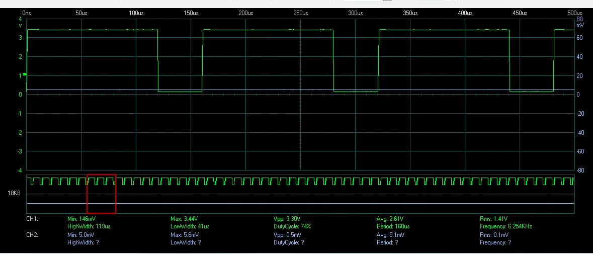
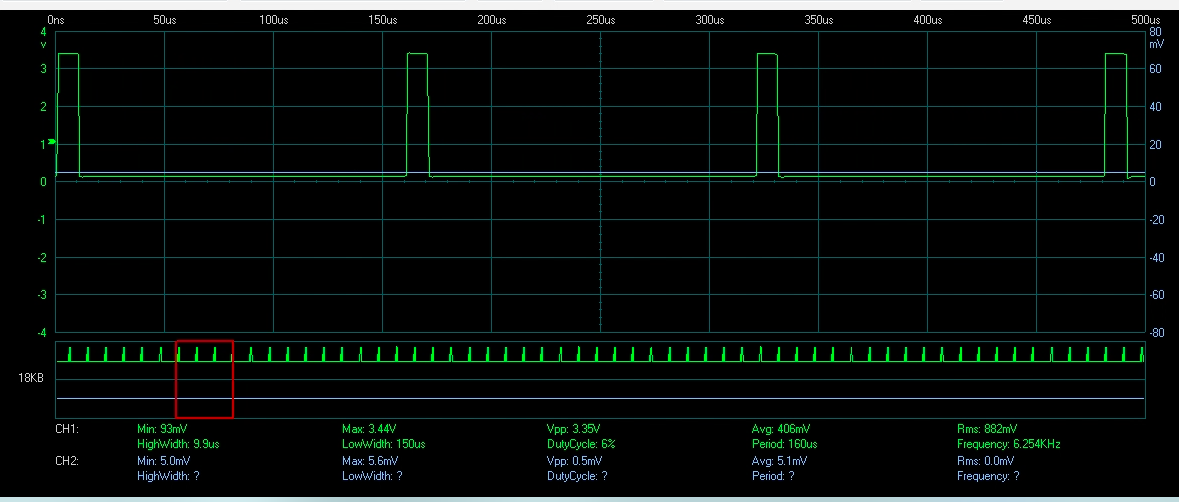
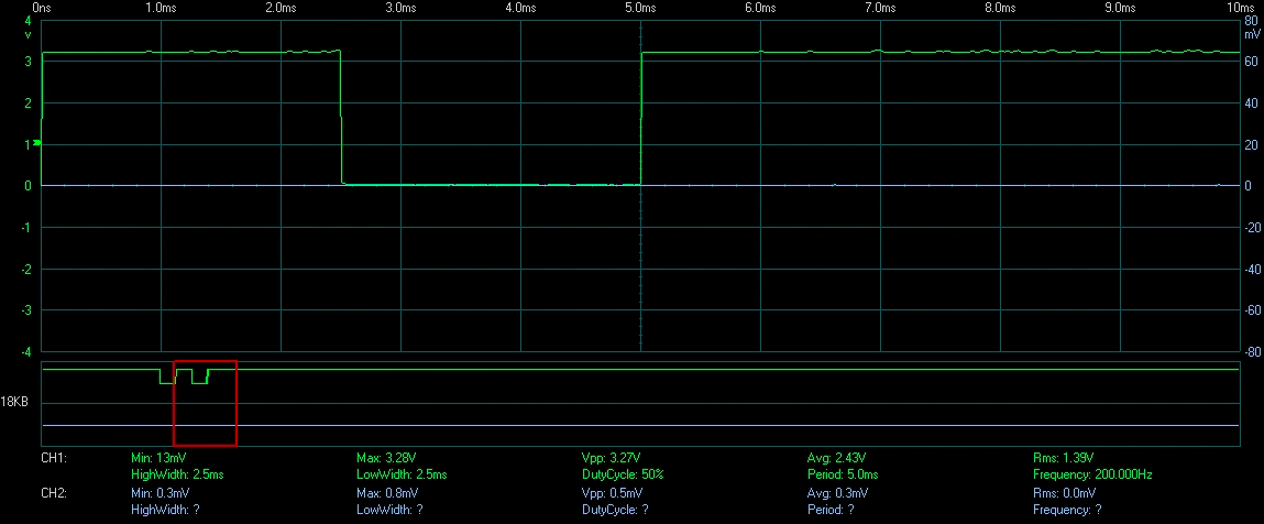
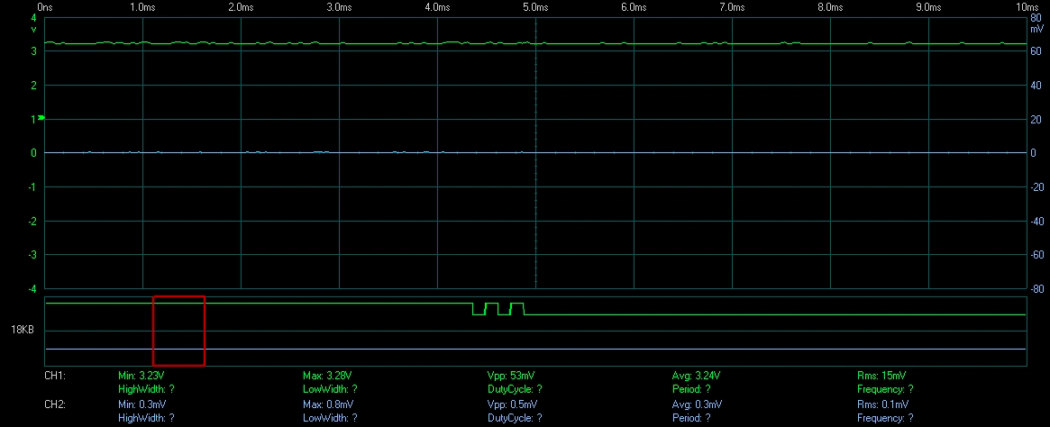
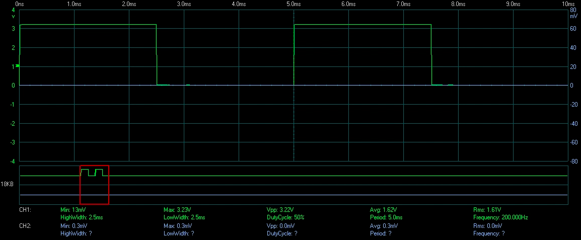
    results of run the program( with Resume (F8)) several times and displayed on an oscilloscope:

    Thank you.

    Regards,

    Amin

  • The AQCTLA register configuration changes I had suggested in a previous post I had intended to be added to the end of the FPU_initEPWM() function examples_setup.c to replace the AQCTLA configuration code that was already there. What was the intention behind putting it in the ISR?

    I see that's your ePWM2 signal in the oscilloscope captures. What do you expect it to look like? Are the values being stored in RFFTin1Buff not what you expect them to be?

    Whitney
  • I changed the code,

    void FPU_initEPWM(void)
    {
        CpuSysRegs.PCLKCR2.bit.EPWM1             =1;  // Enable EPWM1 clocks
        CpuSysRegs.PCLKCR2.bit.EPWM2             =1;  // Enable EPWM1 clocks
        
        //Enable EPWM GPIOs
        InitEPwm1Gpio();
        InitEPwm2Gpio();
        
        EALLOW;
        // EPWM clock divider set to /2
        ClkCfgRegs.PERCLKDIVSEL.bit.EPWMCLKDIV = 1;                
        // Turn off the EPWM clock
        CpuSysRegs.PCLKCR0.bit.TBCLKSYNC       = 0;                
        // Disable SOC on A group
        EPwm1Regs.ETSEL.bit.SOCAEN             = 0;                
        // Select SOC on up-count
        EPwm1Regs.ETSEL.bit.SOCASEL            = 4;                
        // Generate pulse on 1st event
        EPwm1Regs.ETPS.bit.SOCAPRD             = 1;                
        // Set compare A value to 2000 counts
        EPwm1Regs.CMPA.bit.CMPA                = EPWM1_DUTY_CYCLE; 
        // Set period to 4000 counts
        EPwm1Regs.TBPRD                        = EPWM1_PERIOD;     
        // freeze counter
        EPwm1Regs.TBCTL.bit.CTRMODE            = 3;                
        //enable SOCA
        EPwm1Regs.ETSEL.bit.SOCAEN             = 1;                
        EPwm1Regs.TBCTL.bit.HSPCLKDIV          = EPWM_HSPCLKDIV;
        // Disable SOC on A group
        EPwm2Regs.ETSEL.bit.SOCAEN             = 0;                
        // Set compare A value to 10000 counts
        EPwm2Regs.CMPA.bit.CMPA                = EPWM2_DUTY_CYCLE; 
        // Set period to 20000 counts
        EPwm2Regs.TBPRD                        = EPWM2_PERIOD;     
        // freeze counter
        EPwm2Regs.TBCTL.bit.CTRMODE            = 3;                
        EPwm2Regs.TBCTL.bit.HSPCLKDIV          = EPWM_HSPCLKDIV;
        // Clear PWM1A on Zero
     /*   EPwm1Regs.AQCTLA.bit.CAU               = AQ_SET;
        EPwm1Regs.AQCTLA.bit.PRD               = AQ_CLEAR;         
        // Clear PWM2A on Zero
        EPwm2Regs.AQCTLA.bit.CAU               = AQ_SET;           
        EPwm2Regs.AQCTLA.bit.PRD               = AQ_CLEAR;*/
    
         EPwm1Regs.AQCTLA.bit.ZRO               = AQ_SET;
         EPwm1Regs.AQCTLA.bit.CAU               = AQ_CLEAR;
         EPwm2Regs.AQCTLA.bit.ZRO               = AQ_SET;
         EPwm2Regs.AQCTLA.bit.CAU               = AQ_CLEAR;
        
        EDIS;
    }

    the problem is that the stored values on the RFFTin1Buff  is a variable in the time

    I need to start pulses are always the same.

    Regards,

    Amin

  • Okay, did you try my other suggestion about decreasing the dividers on the ePWM clocks to try to get the ePWMs to stay in sync?

    Also, even if they start in sync, they're going to get out of sync. You're currently setting the ePWM1 period to 12 and the ePWM2 period to 31250 which isn't divisible by 12. So you can either reconfigure the ePWM dividers until you're able to get two PRD values that can stay synchronized, or you'll have to resynchronize them by clearing TBCLKSYNC, clearing the TBCTR, and setting TBCLKSYNC.

    For example, in examples_setup.h

    //*****************************************************************************
    // defines
    //*****************************************************************************
    #define CPU_FRQ_200MHZ          1
    #define ADC_SAMPLING_FREQ       100000.0L
    #define EPWM_CLK                100000000   //EPWM_CLOCK is SYSCLK/2
    #define EPWM_CLKDIV             1           //EPWM_CLOCK is SYSCLK/(2*2)
    #define EPWM_HSPCLKDIV          2           //EPWM_CLOCK is SYSCLK/(4*2*2)
    #define EPWM1_PERIOD            EPWM_CLK/(4*2*500000U)
    #define EPWM1_DUTY_CYCLE        EPWM1_PERIOD/2
    #define EPWM2_PERIOD            EPWM_CLK/(4*2*200U)
    #define EPWM2_DUTY_CYCLE        EPWM2_PERIOD/2

    Thanks,

    Whitney

  • Thank you for your help. I changed the code, BreakPoint as follow:
    while(1){
    while(flagInputReady == 0){};
    RFFT_adc_f32(hnd_rfft_adc); // Calculate real FFT (12-bit ADC input) <----------------------------BreakPoint
    ...
    }
    for first run, the result is good and, RFFTin1Buff is:

    But I do not see the same results in the next runs, All indices in the RFFTin1Buff[]  are shifted to RFFTin1Buff[0].

    Regards,

    Amin