This thread has been locked.

If you have a related question, please click the "Ask a related question" button in the top right corner. The newly created question will be automatically linked to this question.

CCS/CCSTUDIO-C2000: PLL problem

Part Number: CCSTUDIO-C2000

Tool/software: Code Composer Studio

I am using C2000, I have a problem using the PLL, when I try to lock it there's a small phase shift that I could not get rid off. I am generating a reference signal that is locked to the AC grid voltage, and then subtract the grid voltage from the generated reference, The output signal should be 180 phase shift from the AC grid voltage as the reference is larger. however it is not. here's my code related to the PLL. 

#include "cla_adc_shared.h"
#include <math.h>
#include "SPLL_1ph.h"

SPLL_1ph spll1;

#define PI_2 6.2831853
#define PWM_TBPRD 50000 //100MHz/PWM_TBPRD/2=Tsw=1/1kHz
#define PWM_TBPRD_HALF 25000
#define PWM_TBPRD_HI 100
#define PWM_TBPRD_LO 1250
#define OCP_LIMIT_HI 4000//2600 //This limit is normal
#define OCP_LIMIT_LO 0//1500 //This limit should be smaller than 1800, issue remained???


// Initialization of PLL
SPLL_1ph_init((float)(60),(float)(0.000025),&spll1);

//PLL to the source voltage
spll1.AC_input= VS_LPF;
SPLL_1ph_run(&spll1);
PLL_PHASE=spll1.theta[0];
// PLL to the source voltage with amplitude of one
PLL_VS = 1*sin((PLL_PHASE/2)*(float)PI_2);
//Load voltage referance
VOr=(float)(Vm*sqrt(2)*PLL_VS);
VOref=(0.545*VOref + 0.455*(float)VOr);
//APF voltage referance
//VSact = (float)(5.6*sqrt(2)*PLL_VS)-0.3;

VSact = (float)(19*0.00073242187*((float)VS_LPF)-0.36);
//Boundry control Calculations
Vd=(float)((VS_LPF)-(VOref));

Thanks in advance,

Radwa

  • Radwa,

    Your post has been assigned to an engineer and is being looked into.

    Thanks,
    Mark
  • www.ti.com/.../sprabt3.pdf

    Please refer to the above application note,

    We observed good correlation and not much phase offset, the matlab script is also included in the app note so you can experiment , understand and solve your problem yourself.
  • Dear Manish, 

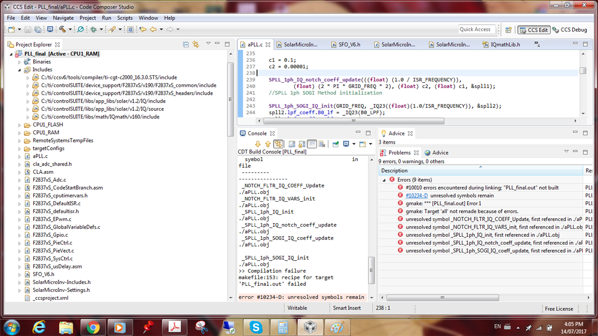
    Thank you for your reply, I am following the example in the PDF and the example on C:\ti\controlSUITE\development_kits\TMDSSOLARUINVKIT_v100\MicroInv_F2803x

    I am encountering errors of unresolved pbs, here are the error and the files I included

    I appreciate ur help

  • Can someone please reply? 

  • Radwa,

    Just to be clear, the issue is not in the solar u inv kit project,

    It is in a new project that you have created to use the PLL module?

    From one of the errors it looks like you have not included #include “Solar_IQ.h” because it complains about functions not being defined..

    Also i see you have added source as a include path in your project, this is not going to work and is not according to the instructions.. i would remove the source folder of the solar lib from the include path
  • Hi Manish, 

    Thanks for your reply.

    Yes It is a project that I have created, I am including the  #include “Solar_IQ.h” so it is not the problem. I have removed the source file as u recommended.

    I have included this:

    #ifndef MATH_TYPE
    #define MATH_TYPE IQ_MATH

    #endif 

    and the error has gone, but now calling the PLL function is not working

    spll1.AC_input =(long)(VS_LPF;

    SPLL_1ph_run(&spll1);

    it says that "expression must have integral type"

    P.S I am now using the function u sent here: 

    https://e2e.ti.com/support/microcontrollers/c2000/f/171/p/118563/829261?tisearch=e2e-quicksearch&keymatch=unresolved%20symbols%20remain#829261

    following the instructions in the PDF

  • Please use only the code that is in controlSUITE , that is the only supported code.

    And present what errors do you have..
  • Dear Manish,

    I appreciate your patience and help

    I am using the code supported by the control suit, I have a problem in generating a sine wave that is looked to my input signal. I think my problem is in calling the function in the ISR. I am currently having no errors. I will attach my code would you please highlight the error.

    P.S: In the PDF u attached, there's is this line: InvSine=spll2.sin<<3; // shift from Q21 to Q24

    I do not get why it is using spll2 while spll1 is defined initially and what's the purpose of shifting the signal.

    #ifndef _SPLL_1ph_H_
    #define _SPLL_1ph_H_
    #define SPLL_Q _IQ21
    #define SPLL_Qmpy _IQ21mpy
    typedef struct{
    int32 B2_notch;
    int32 B1_notch;
    int32 B0_notch;
    int32 A2_notch;
    int32 A1_notch;
    }SPLL_NOTCH_COEFF;
    typedef struct{
    int32 B1_lf;
    int32 B0_lf;
    int32 A1_lf;
    }SPLL_LPF_COEFF;
    typedef struct{
    int32 AC_input;
    int32 theta[2];
    int32 cos[2];
    int32 sin[2];
    int32 wo;
    int32 wn;
    SPLL_NOTCH_COEFF notch_coeff;
    SPLL_LPF_COEFF lpf_coeff;
    int32 Upd[3];
    int32 ynotch[3];
    int32 ylf[2];
    int32 delta_t;
    }
    SPLL_1ph;
    void SPLL_1ph_init(int Grid_freq, long DELTA_T, SPLL_1ph *spll, SPLL_LPF_COEFF lpf_coeff);
    void SPLL_1ph_notch_coeff_update(float delta_T, float wn,float c2, float c1, SPLL_1ph *spll_obj);
    inline void SPLL_1ph_run_FUNC(SPLL_1ph *spll1);
    void SPLL_1ph_init(int Grid_freq, long DELTA_T, SPLL_1ph *spll_obj, SPLL_LPF_COEFF lpf_coeff)
    {
    spll_obj->Upd[0]=SPLL_Q(0.0);
    spll_obj->Upd[1]=SPLL_Q(0.0);
    spll_obj->Upd[2]=SPLL_Q(0.0);
    spll_obj->ynotch[0]=SPLL_Q(0.0);
    spll_obj->ynotch[1]=SPLL_Q(0.0);
    spll_obj->ynotch[2]=SPLL_Q(0.0);
    spll_obj->ylf[0]=SPLL_Q(0.0);
    spll_obj->ylf[1]=SPLL_Q(0.0);
    spll_obj->sin[0]=SPLL_Q(0.0);
    spll_obj->sin[1]=SPLL_Q(0.0);
    spll_obj->cos[0]=SPLL_Q(0.999);
    spll_obj->cos[1]=SPLL_Q(0.999);
    spll_obj->theta[0]=SPLL_Q(0.0);
    spll_obj->theta[1]=SPLL_Q(0.0);
    spll_obj->wn=SPLL_Q(2*3.14*Grid_freq);
    //coefficients for the loop filter
    spll_obj->lpf_coeff.B1_lf=lpf_coeff.B1_lf;
    spll_obj->lpf_coeff.B0_lf=lpf_coeff.B0_lf;
    spll_obj->lpf_coeff.A1_lf=lpf_coeff.A1_lf;
    spll_obj->delta_t=DELTA_T;
    }
    void SPLL_1ph_notch_coeff_update(float delta_T, float wn,float c2, float c1, SPLL_1ph *spll_obj)
    {
    // Note c2<<c1 for the notch to work
    float x,y,z;
    x=(float)(2.0*c2*wn*delta_T);
    y=(float)(2.0*c1*wn*delta_T);
    z=(float)(wn*delta_T*wn*delta_T);
    spll_obj->notch_coeff.A1_notch=SPLL_Q(y-2);
    spll_obj->notch_coeff.A2_notch=SPLL_Q(z-y+1);
    spll_obj->notch_coeff.B0_notch=SPLL_Q(1.0);
    spll_obj->notch_coeff.B1_notch=SPLL_Q(x-2);
    spll_obj->notch_coeff.B2_notch=SPLL_Q(z-x+1);
    }
    inline void SPLL_1ph_run_FUNC(SPLL_1ph *spll_obj)
    {
    //-------------------//
    // Phase Detect //
    //-------------------//
    spll_obj->Upd[0]=SPLL_Qmpy(spll_obj->AC_input,spll_obj->cos[1]);
    //-------------------//
    //Notch filter structure//
    //-------------------//
    spll_obj->ynotch[0]=-SPLL_Qmpy(spll_obj->notch_coeff.A1_notch,spll_obj->ynotch[1])-SPLL_Qmpy(spll_obj->notch_coeff.A2_notch,spll_obj->ynotch[2])+SPLL_Qmpy(spll_obj->notch_coeff.B0_notch,spll_obj->Upd[0])+SPLL_Qmpy(spll_obj->notch_coeff.B1_notch,spll_obj->Upd[1])+SPLL_Qmpy(spll_obj->notch_coeff.B2_notch,spll_obj->Upd[2]);
    // update the Upd array for future
    spll_obj->Upd[2]=spll_obj->Upd[1];
    spll_obj->Upd[1]=spll_obj->Upd[0];
    //---------------------------//
    // PI loop filter //
    //---------------------------//
    spll_obj->ylf[0]=-SPLL_Qmpy(spll_obj->lpf_coeff.A1_lf,spll_obj->ylf[1])+SPLL_Qmpy(spll_obj->lpf_coeff.B0_lf,spll_obj->ynotch[0])+SPLL_Qmpy(spll_obj->lpf_coeff.B1_lf,spll_obj->ynotch[1]);
    //update array for future use
    spll_obj->ynotch[2]=spll_obj->ynotch[1];
    spll_obj->ynotch[1]=spll_obj->ynotch[0];
    spll_obj->ylf[1]=spll_obj->ylf[0];
    //------------------//
    // VCO //
    //------------------//
    spll_obj->wo=spll_obj->wn+spll_obj->ylf[0];
    //integration process to compute sine and cosine
    spll_obj->sin[0]=spll_obj->sin[1]+SPLL_Qmpy((SPLL_Qmpy(spll_obj->delta_t,spll_obj->wo)),spll_obj->cos[1]);
    spll_obj->cos[0]=spll_obj->cos[1]-SPLL_Qmpy((SPLL_Qmpy(spll_obj->delta_t,spll_obj->wo)),spll_obj->sin[1]);
    if(spll_obj->sin[0]>SPLL_Q(0.99))
    spll_obj->sin[0]=SPLL_Q(0.99);
    else if(spll_obj->sin[0]<SPLL_Q(-0.99))
    spll_obj->sin[0]=SPLL_Q(-0.99);
    if(spll_obj->cos[0]>SPLL_Q(0.99))
    spll_obj->cos[0]=SPLL_Q(0.99);
    else if(spll_obj->cos[0]<SPLL_Q(-0.99))
    spll_obj->cos[0]=SPLL_Q(-0.99);
    //compute theta value
    spll_obj->theta[0]=spll_obj->theta[1]+SPLL_Qmpy(SPLL_Qmpy(spll_obj->wo,SPLL_Q(0.159154943)),spll_obj->delta_t);
    if(spll_obj->sin[0]>SPLL_Q(0.0) && spll_obj->sin[1] <=SPLL_Q (0.0))
    {
    spll_obj->theta[0]=SPLL_Q(0.0);
    spll_obj->theta[1]=spll_obj->theta[0];
    spll_obj->sin[1]=spll_obj->sin[0];
    spll_obj->cos[1]=spll_obj->cos[0];
    }
    }
    #endif

    //Main code

    #include "IQmathLib.h"
    #include "SPLL_1ph.h"

    SPLL_1ph spll1;
    SPLL_LPF_COEFF spll_lpf_coef1;

    // Initialization of PLL
    SPLL_1ph_init(60, _IQ21((float)(0.00002)), &spll1,spll_lpf_coef1);
    c1=0.1;
    c2=0.00001;
    SPLL_1ph_notch_coeff_update(((float)(0.00002)),(float)(PI_2*60*2),(float)c2,(float)c1, &spll1);
    #define B0_LPF SPLL_Q(166.877556)
    #define B1_LPF SPLL_Q(-166.322444)
    #define A1_LPF SPLL_Q(-1.0)
    spll_lpf_coef1.B0_lf=B0_LPF;
    spll_lpf_coef1.B1_lf=B1_LPF;
    spll_lpf_coef1.A1_lf=A1_LPF;

    //ISR

    // Use the angle value to compute the sine value
    spll1.AC_input=(long)VS>>3; // Q24 to Q21
    SPLL_1ph_run_FUNC(&spll1);
    VOref=(long)spll1.sin<<3;

    Many thanks,

    Radwa

  • I would suggest you look at examples in controlSUITE C:\ti\controlSUITE\development_kits\TMDSSOLARUINVKIT_v100\MicroInv_F2803x and compare what are the difference.

    Unfortunately debugging customer code is not part of what we can help with unless a device issue is identified.