This thread has been locked.

If you have a related question, please click the "Ask a related question" button in the top right corner. The newly created question will be automatically linked to this question.

CCS/TMS320F28335: Issues with PID controller

Part Number: TMS320F28335
Other Parts Discussed in Thread: C2000WARE, POWERSUITE

Tool/software: Code Composer Studio

Hello,

I am trying to use the DMC pid block in Simulink for closed loop control of an ordinary boost converter on a breadboard. It seems to be giving the right output but the performance of the PID is very worrisome. The output of PID that controls the gate driver of the mosfet is completely unstable, I mean the pulse it yields is unstable. In short, the PID forced to gate driver to operate at either 100% or 0%, as a result, the inductor current was huge. To confirm what I was seeing I simulated the boost converter on Simulink using the ordinary continuous PID controller and compared the results with the one in which I simulated with the DMC PID controller. I discovered that with the DMC inductor current was about x20 with respect to the current gotten when I used the ordinary continuous PID controller. I am convinced there is a major problem.

Additionally, I went through the PID portion of the embedded coder generated C code, the code made complete sense as it is based on ideal PID, I mean I couldn't find any error in the code. So what could be wrong? Or how can I get another tested/good PID controller. Plus, I have also tried the PID controller in the C2000 buck-boost converter example. It didn't work toooooooo. I already have a solid integrator constant, I just need a digital PID to carry it out.

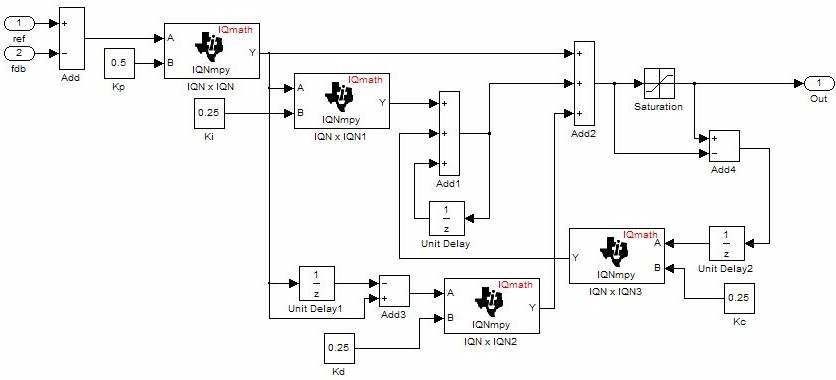
I believe PID is something almost everyone here would know about and probably have used at some point; therefore, I would appreciate tips and assistance. Below is the PID I am talking about (default constants).

Thanks.

David.

  • Consider falling back to a simple proportional controller. If that does not work in an understandable way, then there may be other things wrong.
  • David,

    Structurally your PID diagram looks OK.  I suspect you just don't have the gains right - the default values in your diagram look wrong for a digital controller.  Since this is a discrete time controller you will have to make allowance for the sampling period when you calculate the gains.  

    The buck-boost converter typically has a sample rate of about 100 kHz, or a sample period (T) of 10 us.  When you do the conversion the integral gain get multiplied by T and the derivative gain divided by T, so Ki ends up much smaller than Kd, typically.  

    As suggested in the last post, you might like to start with a simple configuration.  Set Ki, Kd, & Kc to 0, and try to see if you can get it stable with Kp only.  Then, introduce a very small amount of integral action (very small Ki).  You don't need the derivative path for boost converter control, so you ought to be able to get good results just like this.

    One more thing, the way you have integrator anti-windup implemented will work, but there are better ways.  I recommend you look at the Digital Control Library in C2000Ware ().  There are several PID controllers there and since you are using a floating-point device, you should be able to use them easily.

    Regards,

    Richard

  • Thanks Richard.
    I agree that it has to be the constants. I have tried turning all the gains off then increase the Kp and subsequently the Ki but it is still the same thing: I am getting the required output but the duty cycle output is either 1 or 0 and this doesn't make sense. The DMC pid is starting to look bleak. I even discovered a scaling factor of 67108 in the buck-boost controller(pid to 2p2z). I have been trying to find out how they got that constant but I couldn't find any useful information. Can you advise me on that? Maybe if I twitch that it just might help.
  • David,

    I'm wondering if it might be the Q value you have for IQmath.  How do you have the MATH_TYPE and GLOBAL_Q configured?

    Regards,

    Richard

  • Hello Richard,

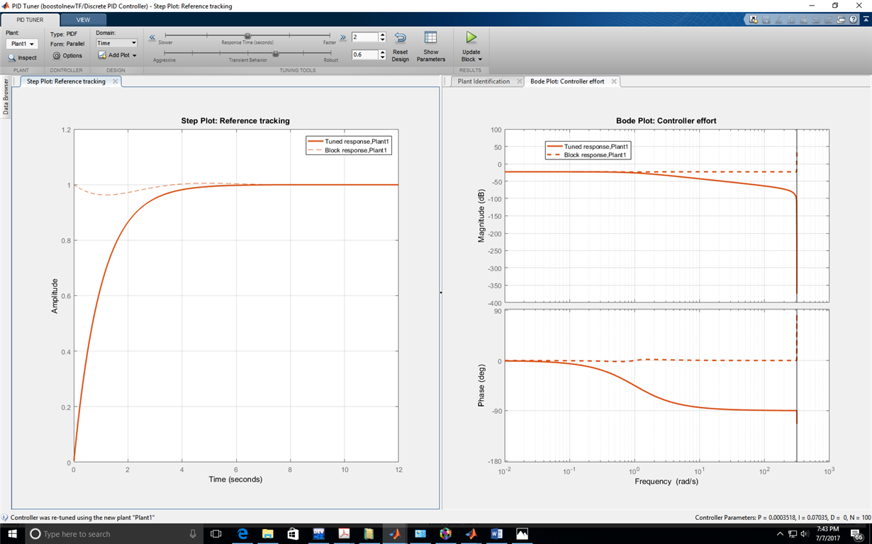
    Having gone through some of your videos on youtube, I tried a more methodical approach to designing the PID. I used frequency response estimation of plant controller and I also used the system Identification toolbox on the simulation I implemented in order to linearize the plant about the PID and get the PID coefficients. The former worked only for step/sine responses, when I tried it with the actual converter simulation, it failed. The constants gotten from the second method gave a super slow response in discrete time mode (about 2 second settling time). Since, I have previously implemented the closed boost converter using analog method (op-amps), I simply decided to discretize the integrator back then (with Ki = 10 and sampling time of 0.01s) and use it with f28335 but it is not working well. I have been on this for over two weeks, it's getting tiring. But I have a feeling it is something small that is holding me back.

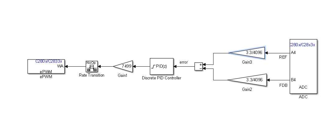
    additionally, I divided the input voltages by 20 to ensure they never go beyond 3.3v.

    I need your advise.

    Kindly find attached the bode plot for the controller effort gotten through the system identification toolbox and the f28335 Simulink model.

    Thanks.

    David
  • Richard said that the sampling period for a boost converter is typically 10 uS.

    "The buck-boost converter typically has a sample rate of about 100 kHz, or a sample period (T) of 10 us."

    Are you running at 10 uSec = 0.00001s or 10 mSec = 0.01s
  • I am running the boost converter pwm at 20kHz but the sampling period for the discretization is 0.01s, I have tried 0.001s too to increase sampling accuracy. For the converter, L=330e-6H, C=100e-6F,Load=100ohms.... I also included the inductor esr.
  • I have an FPGA boost model that I may try your model parameters on. It may not take hold because my baseline is a 200 KHz PWM and you are running at 20 KHz..  I'm currently using the TI powerSUITE tools, and have not used the simulink tools for quite a while, so I am unfamiliar with diagnosing the peculiarities of their process.

    Here is a link to an article that you may like to reference.

    https://www.biricha.com/articles/foundations-part-2d-why-a-pid-controller-is-not-suitable-for-stabilizing-many-power-supply-topologies

    ...

  • Thanks a lot for your help and efforts, I appreciate you.

    I know that at lower duty cycles (around 30%), the converter goes into DCM. Apart from using a higher sampling frequency, one of the solutions I have found for ensuring CCM is designing for a larger inductor using some set of equations, so I am not too worried about that. However, having implemented the closed loop converter on a breadboard (with the same parameters and at the same 20kHz), what really troubles me is how the PID which I have designed with 2 methods (System identification toolbox and Frequency Response plant estimation) have not yielded stable results.

    I have a feeling it is still the PID that is giving me issues. I am totally stumped on this one.

    David.