This thread has been locked.

If you have a related question, please click the "Ask a related question" button in the top right corner. The newly created question will be automatically linked to this question.

CCS/TMS320F28379D: ADC sensing and storing data in Register

Part Number: TMS320F28379D
Other Parts Discussed in Thread: CONTROLSUITE, C2000WARE

Tool/software: Code Composer Studio

Hi all,

          Currently I am working on sensing Input data in ADC ports and storing the same in ADC register. I am using the source code of adc_soc_epwm for getting the output. I am sensing 3.3V right from the MCU card at ADC channel3. The source code is as below:

//###########################################################################
//
// FILE: adc_soc_epwm_cpu01.c
//
// TITLE: ADC triggering via epwm for F2837xD.
//
//! \addtogroup cpu01_example_list
//! <h1> ADC ePWM Triggering (adc_soc_epwm)</h1>
//!
//! This example sets up the ePWM to periodically trigger the ADC.
//!
//! After the program runs, the memory will contain:\n
//! - \b AdcaResults \b: A sequence of analog-to-digital conversion samples from
//! pin A0. The time between samples is determined based on the period
//! of the ePWM timer.
//
//###########################################################################
// $TI Release: F2837xD Support Library v210 $
// $Release Date: Tue Nov 1 14:46:15 CDT 2016 $
// $Copyright: Copyright (C) 2013-2016 Texas Instruments Incorporated -
// http://www.ti.com/ ALL RIGHTS RESERVED $
//###########################################################################

//
// Included Files
//
#include "F28x_Project.h"

//
// Function Prototypes
//
void ConfigureADC(void);
void ConfigureEPWM(void);
void SetupADCEpwm(Uint16 channel);
interrupt void adca1_isr(void);

//
// Defines
//
#define RESULTS_BUFFER_SIZE 8

//
// Globals
//
Uint16 AdcaResults[RESULTS_BUFFER_SIZE];
Uint16 resultsIndex;
volatile Uint16 bufferFull;

void main(void)
{
//
// Step 1. Initialize System Control:
// PLL, WatchDog, enable Peripheral Clocks
// This example function is found in the F2837xD_SysCtrl.c file.
//
InitSysCtrl();

//
// Step 2. Initialize GPIO:
// This example function is found in the F2837xD_Gpio.c file and
// illustrates how to set the GPIO to it's default state.
//
InitGpio(); // Skipped for this example

//
// Step 3. Clear all interrupts and initialize PIE vector table:
// Disable CPU interrupts
//
DINT;

//
// Initialize the PIE control registers to their default state.
// The default state is all PIE interrupts disabled and flags
// are cleared.
// This function is found in the F2837xD_PieCtrl.c file.
//
InitPieCtrl();

//
// Disable CPU interrupts and clear all CPU interrupt flags:
//
IER = 0x0000;
IFR = 0x0000;

//
// Initialize the PIE vector table with pointers to the shell Interrupt
// Service Routines (ISR).
// This will populate the entire table, even if the interrupt
// is not used in this example. This is useful for debug purposes.
// The shell ISR routines are found in F2837xD_DefaultIsr.c.
// This function is found in F2837xD_PieVect.c.
//
InitPieVectTable();

//
// Map ISR functions
//
EALLOW;
PieVectTable.ADCA1_INT = &adca1_isr; //function for ADCA interrupt 1
EDIS;

//
// Configure the ADC and power it up
//
ConfigureADC();

//
// Configure the ePWM
//
ConfigureEPWM();

//
// Setup the ADC for ePWM triggered conversions on channel 0
//
SetupADCEpwm(2);

//
// Enable global Interrupts and higher priority real-time debug events:
//
IER |= M_INT1; //Enable group 1 interrupts
EINT; // Enable Global interrupt INTM
ERTM; // Enable Global realtime interrupt DBGM

//
// Initialize results buffer
//
for(resultsIndex = 0; resultsIndex < RESULTS_BUFFER_SIZE; resultsIndex++)
{
AdcaResults[resultsIndex] = 0;
}
resultsIndex = 0;
bufferFull = 0;

//
// enable PIE interrupt
//
PieCtrlRegs.PIEIER1.bit.INTx1 = 1;

//
// sync ePWM
//
EALLOW;
CpuSysRegs.PCLKCR0.bit.TBCLKSYNC = 1;

//
//take conversions indefinitely in loop
//
do
{
//
//start ePWM
//
EPwm1Regs.ETSEL.bit.SOCAEN = 1; //enable SOCA
EPwm1Regs.TBCTL.bit.CTRMODE = 0; //unfreeze, and enter up count mode

//
//wait while ePWM causes ADC conversions, which then cause interrupts,
//which fill the results buffer, eventually setting the bufferFull
//flag
//
while(!bufferFull);
bufferFull = 0; //clear the buffer full flag

//
//stop ePWM
//
EPwm1Regs.ETSEL.bit.SOCAEN = 0; //disable SOCA
EPwm1Regs.TBCTL.bit.CTRMODE = 3; //freeze counter

//
//at this point, AdcaResults[] contains a sequence of conversions
//from the selected channel
//

//
//software breakpoint, hit run again to get updated conversions
//
// asm(" ESTOP0");
}while(1);
}

//
// ConfigureADC - Write ADC configurations and power up the ADC for both
// ADC A and ADC B
//
void ConfigureADC(void)
{
EALLOW;

//
//write configurations
//
AdcaRegs.ADCCTL2.bit.PRESCALE = 6; //set ADCCLK divider to /4
AdcSetMode(ADC_ADCA, ADC_RESOLUTION_12BIT, ADC_SIGNALMODE_SINGLE);

//
//Set pulse positions to late
//
AdcaRegs.ADCCTL1.bit.INTPULSEPOS = 1;

//
//power up the ADC
//
AdcaRegs.ADCCTL1.bit.ADCPWDNZ = 1;

//
//delay for 1ms to allow ADC time to power up
//
DELAY_US(1000);

EDIS;
}

//
// ConfigureEPWM - Configure EPWM SOC and compare values
//
void ConfigureEPWM(void)
{
EALLOW;
// Assumes ePWM clock is already enabled
EPwm1Regs.ETSEL.bit.SOCAEN = 0; // Disable SOC on A group
EPwm1Regs.ETSEL.bit.SOCASEL = 4; // Select SOC on up-count
EPwm1Regs.ETPS.bit.SOCAPRD = 1; // Generate pulse on 1st event
EPwm1Regs.CMPA.bit.CMPA = 0x0800; // Set compare A value to 2048 counts
EPwm1Regs.TBPRD = 0x1000; // Set period to 4096 counts
EPwm1Regs.TBCTL.bit.CTRMODE = 3; // freeze counter
EDIS;
}

//
// SetupADCEpwm - Setup ADC EPWM acquisition window
//
void SetupADCEpwm(Uint16 channel)
{
Uint16 acqps;

//
//determine minimum acquisition window (in SYSCLKS) based on resolution
//
if(ADC_RESOLUTION_12BIT == AdcaRegs.ADCCTL2.bit.RESOLUTION)
{
acqps = 14; //75ns
}
else //resolution is 16-bit
{
acqps = 63; //320ns
}

//
//Select the channels to convert and end of conversion flag
//
EALLOW;
AdcaRegs.ADCSOC2CTL.bit.CHSEL = channel; //SOC0 will convert pin A0
AdcaRegs.ADCSOC2CTL.bit.ACQPS = acqps; //sample window is 100 SYSCLK cycles
AdcaRegs.ADCSOC2CTL.bit.TRIGSEL = 5; //trigger on ePWM1 SOCA/C
AdcaRegs.ADCINTSEL1N2.bit.INT1SEL = 0; //end of SOC0 will set INT1 flag
AdcaRegs.ADCINTSEL1N2.bit.INT1E = 1; //enable INT1 flag
AdcaRegs.ADCINTFLGCLR.bit.ADCINT1 = 1; //make sure INT1 flag is cleared
EDIS;
}

//
// adca1_isr - Read ADC Buffer in ISR
//
interrupt void adca1_isr(void)
{
AdcaResults[resultsIndex++] = AdcaResultRegs.ADCRESULT2;
if(RESULTS_BUFFER_SIZE <= resultsIndex)
{
resultsIndex = 0;
bufferFull = 1;
}

AdcaRegs.ADCINTFLGCLR.bit.ADCINT1 = 1; //clear INT1 flag
PieCtrlRegs.PIEACK.all = PIEACK_GROUP1;
}

//
// End of file
// ]

But to surprise no data is getting stored in AdcaResults variable. Can anyone suggest the missing command in the above source code.

Thanks in advance.

Regards

Sumanta

  • Hi Sumanta,

    Does this work with the unchanged example from ControlSUITE? If not, you should focus on HW debug like checking the channel connections, supply rails, ADC reference, etc. If it does work unchanged, go back to that code and make one change at a time and verify correct operation at each step.
  • Hi Devin,

    Thanks for your response. I am using the ADC channel (ADCINA2) and accordingly configured in my source code. I would like to know what changes are you suggesting to do in the program or any other ADC program that can be debugged and checked for storing data from ADC analog input to ADC registers.

    Thanks in advance.

    Regards
    Sumanta
  • Hi Sumanta,

    I think by default the example is set to convert on channel A0 by default? Try to get that to work before making changes to the stock example. If you can't get that to work, the issue is probably HW/Setup related (e.g. VDDA suppy rail is not correct, VREF pin is not supplied, input stimulus is hooked up to the wrong header and/or pin, etc.). If A0 works but not A2, then you should carefully consider what SW changes you have made to determine if they are correct/complete.
  • Hi Devin,

    Can you tell me in the above source code what will be the corresponding configuration settings for channel ADCINA2 so that ADC outputs getting stored in register can be obtained in Code Composer Studio window environment. Please suggest.

    Thanks in advance.

    Regards
    Sumanta
  • Hi Devin,

    The modified source code is as below:
    [
    //
    // Included Files
    //
    #include "F28x_Project.h"
    #include <stdint.h>
    #include <stdbool.h>
    #include "inc/hw_types.h"
    #include "inc/hw_memmap.h"
    #include "inc/hw_can.h"
    #include "driverlib/can.h"

    //
    // Function Prototypes
    //
    void ConfigureADC(void);
    void ConfigureEPWM(void);
    void SetupADCEpwm(Uint16 channel);
    interrupt void adca1_isr(void);

    //
    // Defines
    //
    #define RESULTS_BUFFER_SIZE 8

    // Globals
    //
    volatile unsigned long g_ulMsgCount = 0; // A counter that keeps track of the
    // number of times the transmit was
    // successful.
    volatile unsigned long g_bErrFlag = 0; // A flag to indicate that some
    // transmission error occurred.

    Uint16 AdcaResults[RESULTS_BUFFER_SIZE];
    Uint16 resultsIndex;
    volatile Uint16 bufferFull;

    //
    // Main
    //
    void main(void)
    {
    tCANMsgObject sTXCANMessage;
    tCANMsgObject sRXCANMessage;
    unsigned char ucTXMsgData[8]={'0','0','0','0','0','0','0','0'}, ucRXMsgData[8]={'0','0','0','0','0','0','0','0'};

    //
    // Step 1. Initialize System Control:
    // PLL, WatchDog, enable Peripheral Clocks
    // This example function is found in the F2837xD_SysCtrl.c file.
    //
    InitSysCtrl();

    //
    // Step 2. Initialize GPIO:8
    // This example function is found in the F2837xD_Gpio.c file and
    // illustrates how to set the GPIO to its default state.
    //


    InitGpio();
    GPIO_SetupPinMux(36, GPIO_MUX_CPU1, 6); //GPIO30 - CANRXA
    GPIO_SetupPinMux(37, GPIO_MUX_CPU1, 6); //GPIO31 - CANTXA
    GPIO_SetupPinOptions(36, GPIO_INPUT, GPIO_ASYNC);
    GPIO_SetupPinOptions(37, GPIO_OUTPUT, GPIO_PUSHPULL);

    //
    // Initialize the CAN controller
    //
    CANInit(CANA_BASE);

    //
    // Setup CAN to be clocked off the M3/Master subsystem clock
    //
    CANClkSourceSelect(CANA_BASE, 0);

    //
    // Set up the bit rate for the CAN bus. This function sets up the CAN
    // bus timing for a nominal configuration. You can achieve more control
    // over the CAN bus timing by using the function CANBitTimingSet() instead
    // of this one, if needed.
    // In this example, the CAN bus is set to 500 kHz. In the function below,
    // the call to SysCtlClockGet() is used to determine the clock rate that
    // is used for clocking the CAN peripheral. This can be replaced with a
    // fixed value if you know the value of the system clock, saving the extra
    // function call. For some parts, the CAN peripheral is clocked by a fixed
    // 8 MHz regardless of the system clock in which case the call to
    // SysCtlClockGet() should be replaced with 8000000. Consult the data
    // sheet for more information about CAN peripheral clocking.
    //
    CANBitRateSet(CANA_BASE, 200000000, 500000);

    //
    // Step 3. Clear all interrupts and initialize PIE vector table:
    // Disable CPU interrupts
    //
    DINT;

    //
    // Initialize the PIE control registers to their default state.
    // The default state is all PIE interrupts disabled and flags
    // are cleared.
    // This function is found in the F2837xD_PieCtrl.c file.
    //
    InitPieCtrl();

    //
    // Disable CPU interrupts and clear all CPU interrupt flags:
    //
    IER = 0x0000;
    IFR = 0x0000;

    //
    // Initialize the PIE vector table with pointers to the shell Interrupt
    // Service Routines (ISR).
    // This will populate the entire table, even if the interrupt
    // is not used in this example. This is useful for debug purposes.
    // The shell ISR routines are found in F2837xD_DefaultIsr.c.
    // This function is found in F2837xD_PieVect.c.
    //
    InitPieVectTable();

    //
    // Map ISR functions
    //
    EALLOW;
    PieVectTable.ADCA1_INT = &adca1_isr; //function for ADCA interrupt 1
    EDIS;

    //
    // Configure the ADC and power it up
    //
    ConfigureADC();

    //
    // Configure the ePWM
    //
    ConfigureEPWM();

    //
    // Setup the ADC for ePWM triggered conversions on channel 0
    //
    SetupADCEpwm(2);

    //
    // Enable global Interrupts and higher priority real-time debug events:
    //
    IER |= M_INT1; //Enable group 1 interrupts
    EINT; // Enable Global interrupt INTM
    ERTM; // Enable Global realtime interrupt DBGM

    //
    // Initialize results buffer
    //
    for(resultsIndex = 0; resultsIndex < RESULTS_BUFFER_SIZE; resultsIndex++)
    {
    AdcaResults[resultsIndex] = 0;
    }
    resultsIndex = 0;
    bufferFull = 0;

    //
    // enable PIE interrupt
    //
    PieCtrlRegs.PIEIER1.bit.INTx1 = 1;

    //
    // sync ePWM
    //
    EALLOW;
    CpuSysRegs.PCLKCR0.bit.TBCLKSYNC = 1;

    //
    //take conversions indefinitely in loop
    //
    do
    {
    //
    //start ePWM
    //
    EPwm1Regs.ETSEL.bit.SOCAEN = 1; //enable SOCA
    EPwm1Regs.TBCTL.bit.CTRMODE = 0; //unfreeze, and enter up count mode

    //
    //wait while ePWM causes ADC conversions, which then cause interrupts,
    //which fill the results buffer, eventually setting the bufferFull
    //flag
    //
    while(!bufferFull);
    bufferFull = 0; //clear the buffer full flag

    //
    //stop ePWM
    //
    EPwm1Regs.ETSEL.bit.SOCAEN = 0; //disable SOCA
    EPwm1Regs.TBCTL.bit.CTRMODE = 3; //freeze counter

    //
    //at this point, AdcaResults[] contains a sequence of conversions
    //from the selected channel
    //

    //
    //software breakpoint, hit run again to get updated conversions
    //
    // asm(" ESTOP0");
    }while(1);
    }

    //
    // ConfigureADC - Write ADC configurations and power up the ADC for both
    // ADC A and ADC B
    //
    void ConfigureADC(void)
    {
    EALLOW;

    //
    //write configurations
    //
    AdcaRegs.ADCCTL2.bit.PRESCALE = 6; //set ADCCLK divider to /4
    AdcSetMode(ADC_ADCA, ADC_RESOLUTION_12BIT, ADC_SIGNALMODE_SINGLE);

    //
    //Set pulse positions to late
    //
    AdcaRegs.ADCCTL1.bit.INTPULSEPOS = 1;

    //
    //power up the ADC
    //
    AdcaRegs.ADCCTL1.bit.ADCPWDNZ = 1;

    //
    //delay for 1ms to allow ADC time to power up
    //
    DELAY_US(1000);

    EDIS;
    }

    //
    // ConfigureEPWM - Configure EPWM SOC and compare values
    //
    void ConfigureEPWM(void)
    {
    EALLOW;
    // Assumes ePWM clock is already enabled
    EPwm1Regs.ETSEL.bit.SOCAEN = 0; // Disable SOC on A group
    EPwm1Regs.ETSEL.bit.SOCASEL = 4; // Select SOC on up-count
    EPwm1Regs.ETPS.bit.SOCAPRD = 1; // Generate pulse on 1st event
    EPwm1Regs.CMPA.bit.CMPA = 0x0800; // Set compare A value to 2048 counts
    EPwm1Regs.TBPRD = 0x1000; // Set period to 4096 counts
    EPwm1Regs.TBCTL.bit.CTRMODE = 3; // freeze counter
    EDIS;
    }

    //
    // SetupADCEpwm - Setup ADC EPWM acquisition window
    //
    void SetupADCEpwm(Uint16 channel)
    {
    Uint16 acqps;

    //
    //determine minimum acquisition window (in SYSCLKS) based on resolution
    //
    if(ADC_RESOLUTION_12BIT == AdcaRegs.ADCCTL2.bit.RESOLUTION)
    {
    acqps = 14; //75ns
    }
    else //resolution is 16-bit
    {
    acqps = 63; //320ns
    }

    //
    //Select the channels to convert and end of conversion flag
    //
    EALLOW;
    AdcaRegs.ADCSOC0CTL.bit.CHSEL = 2; //SOC0 will convert pin A0
    AdcaRegs.ADCSOC0CTL.bit.ACQPS = acqps; //sample window is 100 SYSCLK cycles
    AdcaRegs.ADCSOC0CTL.bit.TRIGSEL = 5; //trigger on ePWM1 SOCA/C
    AdcaRegs.ADCINTSEL1N2.bit.INT1SEL = 0; //end of SOC0 will set INT1 flag
    AdcaRegs.ADCINTSEL1N2.bit.INT1E = 1; //enable INT1 flag
    AdcaRegs.ADCINTFLGCLR.bit.ADCINT1 = 1; //make sure INT1 flag is cleared
    EDIS;
    }

    //
    // adca1_isr - Read ADC Buffer in ISR
    //
    interrupt void adca1_isr(void)
    {
    AdcaResults[resultsIndex++] = AdcaResultRegs.ADCRESULT0;

    if(RESULTS_BUFFER_SIZE <= resultsIndex)
    {
    resultsIndex = 0;
    bufferFull = 1;
    }

    AdcaRegs.ADCINTFLGCLR.bit.ADCINT1 = 1; //clear INT1 flag
    PieCtrlRegs.PIEACK.all = PIEACK_GROUP1;
    }

    //
    // End of file
    //

    //
    // Enable test mode and select external loopback
    //
    //HWREG(CANA_BASE + CAN_O_CTL) |= CAN_CTL_TEST;
    //HWREG(CANA_BASE + CAN_O_TEST) = CAN_TEST_EXL;

    //
    // Enable the CAN for operation.
    //
    CANEnable(CANA_BASE);

    //
    // Initialize the message object that will be used for sending CAN
    // messages. The message will be 4 bytes that will contain an incrementing
    // value. Initially it will be set to 0.
    //
    //*(unsigned long *)ucTXMsgData = 0;
    sTXCANMessage.ui32MsgID = 1; // CAN message ID - use 1
    sTXCANMessage.ui32MsgIDMask = 0; // no mask needed for TX
    sTXCANMessage.ui32Flags = MSG_OBJ_TX_INT_ENABLE; // enable interrupt on TX
    sTXCANMessage.ui32MsgLen = sizeof(ucTXMsgData); // size of message is 4
    sTXCANMessage.pucMsgData = ucTXMsgData; // ptr to message content

    //
    // Initialize the message object that will be used for receiving CAN
    // messages.
    //
    /* *(unsigned long *)ucRXMsgData = 0;
    sRXCANMessage.ui32MsgID = 1; // CAN message ID - use 1
    sRXCANMessage.ui32MsgIDMask = 0; // no mask needed for TX
    sRXCANMessage.ui32Flags = MSG_OBJ_NO_FLAGS;
    sRXCANMessage.ui32MsgLen = sizeof(ucRXMsgData); // size of message is 4
    sRXCANMessage.pucMsgData = ucRXMsgData; // ptr to message content
    */
    //
    // Setup the message object being used to receive messages
    //
    //CANMessageSet(CANA_BASE, 2, &sRXCANMessage, MSG_OBJ_TYPE_RX);

    //
    // Enter loop to send messages. A new message will be sent once per
    // second. The 4 bytes of message content will be treated as an unsigned
    // long and incremented by one each time.
    //
    for(;;)
    {
    ucTXMsgData[0] = AdcaResults[0];
    ucTXMsgData[1] = AdcaResults[1];
    ucTXMsgData[2] = AdcaResults[2];
    ucTXMsgData[3] = AdcaResults[3];
    ucTXMsgData[4] = AdcaResults[4];
    ucTXMsgData[5] = AdcaResults[5];
    ucTXMsgData[6] = AdcaResults[6];
    ucTXMsgData[7] = AdcaResults[7];


    //
    // Send the CAN message using object number 1 (not the same thing as
    // CAN ID, which is also 1 in this example). This function will cause
    // the message to be transmitted right away.
    //
    CANMessageSet(CANA_BASE, 1, &sTXCANMessage, MSG_OBJ_TYPE_TX);

    //
    // Now wait 1 second before continuing
    //
    DELAY_US(1000*1000);

    //
    // Get the receive message
    //
    //CANMessageGet(CANA_BASE, 2, &sRXCANMessage, true);

    //
    // Ensure the received data matches the transmitted data
    //
    /* if((*(unsigned long *)ucTXMsgData) != (*(unsigned long *)ucRXMsgData))
    {
    asm(" ESTOP0");
    }
    */
    //
    // Increment the value in the transmitted message data.
    //
    //(*(unsigned long *)ucTXMsgData)++;
    }
    }

    //
    // End of file
    //
    ]

    On debugging it is giving error at the following lines:

    1) CANEnable(CANA_BASE);

    2) sTXCANMessage.ui32MsgID = 1; // CAN message ID - use 1
    sTXCANMessage.ui32MsgIDMask = 0; // no mask needed for TX
    sTXCANMessage.ui32Flags = MSG_OBJ_TX_INT_ENABLE; // enable interrupt on TX
    sTXCANMessage.ui32MsgLen = sizeof(ucTXMsgData); // size of message is 4
    sTXCANMessage.pucMsgData = ucTXMsgData;

    3) for(;;)
    {
    ucTXMsgData[0] = AdcaResults[0];
    ucTXMsgData[1] = AdcaResults[1];
    ucTXMsgData[2] = AdcaResults[2];
    ucTXMsgData[3] = AdcaResults[3];
    ucTXMsgData[4] = AdcaResults[4];
    ucTXMsgData[5] = AdcaResults[5];
    ucTXMsgData[6] = AdcaResults[6];
    ucTXMsgData[7] = AdcaResults[7];


    //
    // Send the CAN message using object number 1 (not the same thing as
    // CAN ID, which is also 1 in this example). This function will cause
    // the message to be transmitted right away.
    //
    CANMessageSet(CANA_BASE, 1, &sTXCANMessage, MSG_OBJ_TYPE_TX);

    //
    // Now wait 1 second before continuing
    //
    DELAY_US(1000*1000);

    //
    // Get the receive message
    //
    //CANMessageGet(CANA_BASE, 2, &sRXCANMessage, true);

    //
    // Ensure the received data matches the transmitted data
    //
    /* if((*(unsigned long *)ucTXMsgData) != (*(unsigned long *)ucRXMsgData))
    {
    asm(" ESTOP0");
    }
    */
    //
    // Increment the value in the transmitted message data.
    //
    //(*(unsigned long *)ucTXMsgData)++;
    }
    }


    Please suggest if any significant command is missing in the above source code.

    Thanks in advance.


    Regards
    Sumanta
  • Hi Sumanta,

    We don't typically directly debug code as a first step in trouble shooting.  Please see my previously posted debug questions and try these out and report back with exactly what is/isn't working and then we can take additional debug steps as necessary.

  • Hi Devin,

                    I will explain the problem which I am facing presently reg. data transmission between 2 MCUs. 

    1) In MCU1, data is getting sensed from ADCIN port and is being stored in Transmitter (TX) register of CAN port.

    2) From (TX) register, data is getting transferred which should be received by Receiver (RX) register of MCU2.

    The block diagram of operation is as shown in the Attachment figure:

    On debugging the program data is getting sensed in ADC register which is getting stored in TX register in MCU1. But MCU2 RX register is not able to retrieve the same data. It is sensing data whenever the ADCIN of MCU2 is given external inputs.

    Is it reqd. to configure the ADC of MCU2 separately to receive the data and finally to check the DAC output which will be same as the ADC Input.

    Please suggest.

    Thanks in advance.

    Regards

    Sumanta


    Dr. Thanga Raj Chelliah

  • Hi Sumanta,

    Devin is away on vacation so I'll help as much as i can.

    This is my understanding of what you are trying to do:
    1. ADC conversion is done on MCU1.
    2. This conversion result is broadcast on the CAN bus by MCU1.
    3. MCU2 retrieves this conversion result on the CAN bus and writes it to the DAC.

    Looks like you are able to convert on MCU1 but cannot transmit the conversion result to MCU2. The issue you are facing is not a ADC or DAC problem and more of a CAN transmission problem. Please look at the CAN examples in C2000Ware to familiarize yourself with how the CAN operates and if you ran into any issues with those, you can post the CAN question separately and the right CAN expert will address those questions.
  • Hi Frank,

                     As you have correctly understood, presently data transmission between 2 MCU cards are being carried out through CAN port of DSP via

    CAN bus. I will explain regarding the task which I want to perform and the difficulty which I am facing at present:

    1) In case of any fault in converter input data (message) will get sensed through ADC port of MCU1 which will be transmitted to MCU2 via CAN

        mechanism.

    2) Once the MCU2 has received the data it will send signal to the auxillary ports (say DAC, QEP or PWM) to perform a particular operation (say

        blinking an LED indicating fault or turning off the PWM signal).

    So now I am trying to generate an event (say changing Vin of ADC channel from 0 to +3.3V), storing the corresponding data in ADC register of

    MCU1 and sending the same to MCU2 which in turn will blink an LED.

    Please suggest any idea for its implementation in the source code.

    Thanks in advance.

    Regards

    Sumanta
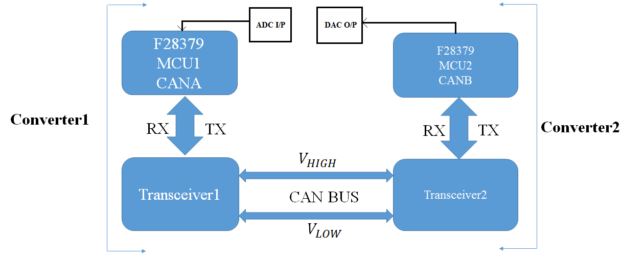
     

  • Sumanta,

    What you are trying to do is broken up fairly cleanly into 3 distinct pieces that it shouldn't be too hard to implement. There is starting code in C2000Ware that should help with the 3 pieces. My recommendation will be to write and test the 3 pieces of code separately and then finally merge them after you have verified everything is working correctly.

    This can be achieved through interrupts. This is one-way i think you can approach it.

    1. Write code that converts on MCU1. The adc_soc examples should get you started.

    2. Write code that just purely tests CAN transmission between 2 MCUs. The can_external_transmit example should get you started.

    3. Write code that lights an LED. The gpio_toggle example should get you started.

    After you get the individual pieces working, you can then glue them together and it should look like this.

    Trigger the ADC to convert a signal when the fault happens. The ADC has multiple trigger sources. After the ADC finishes converting, it fires off an interrupt that initiates the CAN transmission on MCU1. MCU2 receives a transmission interrupt and reads the data from the CAN transmission bus. After receiving the data, it then toggles the LEDs.

    The example codes might not necessarily do exactly what you are looking for but should be enough to get you started.

  • Hi Frank,

    Presently I am sensing 3.3V at ADC input which is getting digitised as : [2028, 2051, 2022, 2040, 2055, 2042, 2037, 2039]. The above data is getting sent from MCU1 to MCU2. But in MCU2, the data is obtained as : [237, 241, 243, 240, 245, 246, 243, 246].

    Please suggest the reason behind the dissimilarity in Transmitted and Received data and how it can be solved.

    Thanks in advance.


    Regards
    Sumanta
  • Sumanta,

    Are you still transmitting data between the 2 MCUs using CAN? Looking at the transmitted and received data, it doesn't look like a simple case of a dropped byte or re-arranged bytes. Did you troubleshoot the transmission problem by taking the ADC out of the equation and just creating and transmitting a dummy array?

    I'm not a CAN expert so to get a better and more accurate response about the transmission issue you are facing, you would have to create a new post about the CAN transmission issue.

    By the way, if you are sensing 3.3V at the ADC input, you should be reading something very close to full scale, 4095.

  • Hi Frank,

                    Actually I am trying to accomodate 16 bit of data in 8 bit space in Transmitter and Receiver variable. So even if I am sensing 3.3 V at the

    ADC input it is displaying 2048 instead of 4096 and while receiving in the Receiver MCU value of 256 is getting obtained. Can you suggest how to

    have the complete conversion of data so that there is no data loss in Transmitting and Receiving between two MCU cards.

    Regards

    Sumanta

  • Sumanta,

    As mentioned before, you should split the problem and debug steps into 2 because you are facing two completely different issues.

    1. First issue is the ADC conversion issue where you are seeing 2048 instead of 4095. You should debug this separately independent of the CAN. The adc_soc examples should help.

    2. Second issue is you are transmitting 2048 through CAN but receiving 256. You should also debug this separately independent of the ADC. Transmit dummy numbers and see if you are able to receive them correctly. Since this is an ADC thread, if you are unable to resolve this 2nd part, create a new post about the CAN transmission issue.

  • Hi Frank,

                    Sorry for late reply. Actually I am able to convert the 16-bit ADC input data i.e [2428, 2433, 2426,.....] into two 8-bit data as: 

    [128, 131, 129,......] and [9, 9, 9,......] in Transmitter MCU so as to accomodate the individual 8-bits in CAN TX msg variable. Now the problem that I

    am facing is regarding combining two 8-bits data and regenerating 16-bit in the Receiver MCU. Will it be an arithmetic addition of two 8-bits data or

    it requires some logic addition as done while separating 8-bits from the 16-bit data. Please suggest.

    Thanks in advance.

    Regards

    Sumanta  
  • Hi Sumanta,

    The strategy you are going to want to take here is to write a function in C to re-combine the two bytes. Feed the function dummy data and observe the output. If the output is not correct, adjust your algorithm and try again until it works for a representative set of possible inputs.

    You are going to need to reverse the steps you used to unpack the data in order to re-assemble it. Adding the two bytes will not work. You can verify this experimentally via the above method.
  • Hi Sumantha,

    For the 16-bit ADC conversion data, no special math operation is needed. Just move the 8-bit lsb conversion data to the 1st CAN message byte and the 8-bit msb conversion data to the 2nd CAN message byte during transmission. Upon CAN message reception, combine (not add) the 2nd CAN message byte with 1st message byte to get the 16-bit conversion data.

    Best regards,
    Joseph
  • Hi Joseph,

                      I have tested 16-bit data transmission in loopback mode. I am able to see the following data in Transmitter and receiver variable:

    ucTXMsgdata = [2428, 2433, 2426, 2442, 2434, 2434, 2421, 2433],

    ucRXMsgdata = [2428, 2433, 2426, 2442, 2434, 2434, 2421, 2433], for 3.3 volts ADC input

    But the problem I am facing is with data transmission between 2 MCUs as the receiver variable corresponding to Receiver MCU is not able to receive the 16-bit data. Please suggest if you have faced the similar problem.

                      Thanks in advance.

    Regards

    Sumanta 
  • Hi Sumanta,

    I am assuming you have done all basic checks with your network of 2 MCUs communicating through the CAN bus:

    1.) Checked that each MCU's CAN RX/TX pins are properly configured and assigned (through GPIO controls) and connected to a transceiver and its output connects to CANL/H lines.

    2.) The transceivers used on both MCU nodes are3.3V level compatible, and are powered up correctly.

    3.) For debugging purposes, use the same CAN time base and baud rate.

    4.) When you probe the CAN bus with a scope, you are able to see some activity  when you attempt to send data through the CAN module.

    Once you confirm above items in your setup, then data transmission and reception should be straightforward.  The receiver not able to accept the 16-bit ADC conversion data really does not tell us a lot.  You would need to isolate where in your code the transmission (or reception) breaks.  Looks to me like you have fixed your ADC conversion issues and with the loopback test, you are able to confirm that data is going out of the TX pin and coming into the RX terminal.  This is a good start, but you would have to assure that the data you are transmitting is properly going into the CAN bus, hence my suggestion to do the basic CAN interfacing checks above.

    Hope this helps.

    Regards,

    Joseph

  • Hi Joseph,

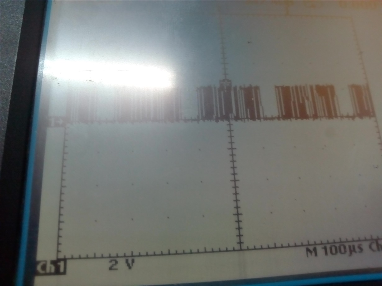
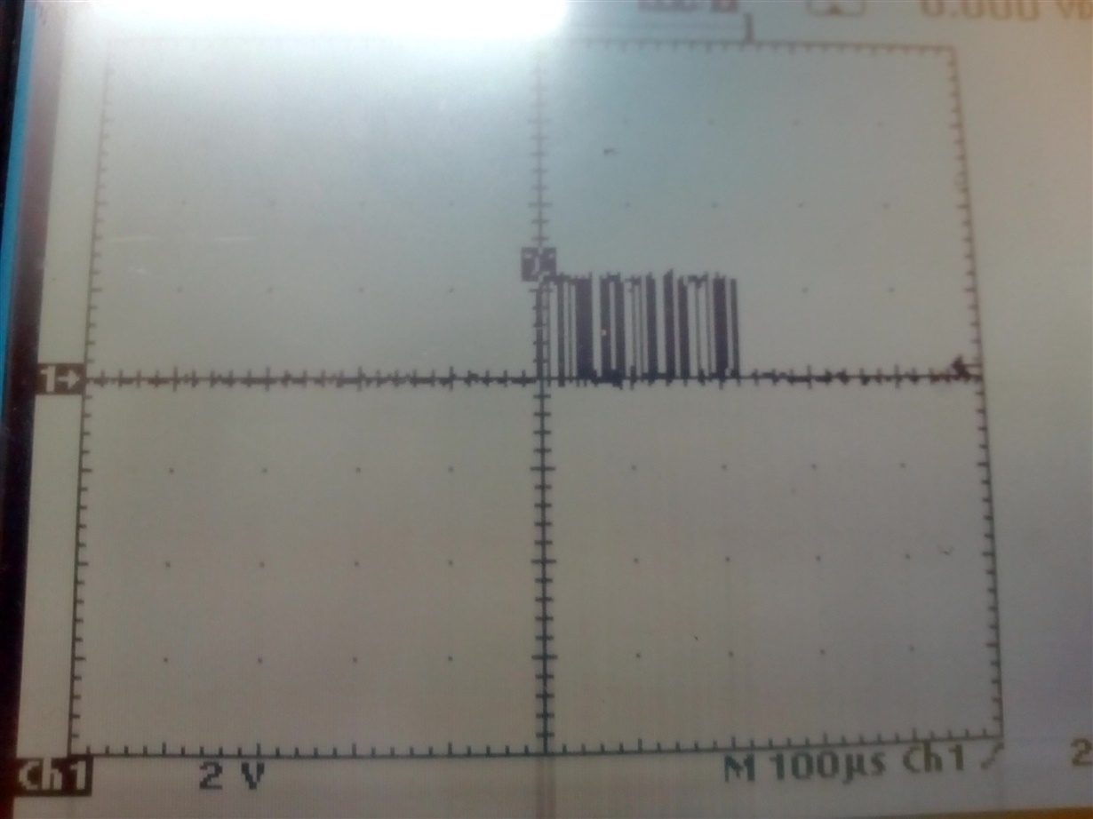
                       Thanks for your suggestion. Basically I am using 2 MCUs with same circuits and ICs. As you have mentioned, I have checked the configurations of each MCUs with GPIO controls, both are 3.3 volts compatible, same CAN time base and baud rate are used in the source codes. I am attaching the waveforms (a) with only Transmitter MCU remaining active and (b) with both Transmitter and Receiver MCUs remaining active for demonstrating the activity of sending data through the CAN module.

    But same data as of transmitter variable is not getting displayed in the receiver variable. Please suggest whether the signals on the CAN bus are proper. Moreover I need to have 20 variables data transmission at the same instant between 2 MCUs. Please suggest also regarding the same.

    Thanks in advance.

    Regards

    Sumanta  

  • Hi Sumanta,

    Can you make a simple debug code that would transmit known fixed values to the CAN bus (constant values as opposed to ADC conversion values as these may be dynamic depending on the signal being converted). It would be easier for you to debug the code if you start with fixed known values being transmitted to the CAN bus.

    Regards,
    Joseph
  • Hi Joseph,

                      Thanks for your suggestion. I am running the CAN code in Loopback mode in order to achieve a particular objective. I have defined a fixed set of two Input data as below:

    Uint16 ucTXMsgData1[8] = {2428,2433,2426,2442,2434,2434,2421,2433}; ucRXMsgData1[8]; 
    Uint16 ucTXMsgData2[8] = {2428,2433,2426,2442,2434,2434,2421,2433}; ucRXMsgData2[8]

    After running the code if we want to update any value in the Transmitter variable, the value is getting changed in 8-bit format, i.e 2429 in transmitter yields 129 at the receiver input. Can you suggest the possible modifications in the source code for receiving the exact data as transmitted.

    Thanks in advance.

    Regards

    Sumanta

  • Hi Sumanta,

    Ok, now your problem makes sense.  You are passing 16-bit numbers to the TX buffer, however the buffer is defined as char which is 8-bit wide.  What happens is that the upper 8 bits of the 16-bit number you wanted to transmit gets truncated and it type casted to char type and the buffer will only represent the lower 8 bits.  For the case of your example:

        - Number 2429 in binary is represented as 16-bit binary as 000 1001 0111 1101

        - When you move 2429 to the TX buffer, only the lower 8 bits are accommodated (0111 1101) so 2429 will be 125 in 8-bit representation

    Here is what you have to do.  Break out your numbers in 8-bit format before moving them to the TX buffer.  Note that one CAN message only allows you to send a maximum of 8 bytes of data (8 of 8-bit number or 8 of char type number).  This means you can only send 4 16-bit conversion data in one message (not 8).  Let's say your conversion data is defined as adcconv of type Uint16.  You can try the following prior to transmission:

    Uint16 adcconv;

    // first ADC conversion result

    adcconv = AdcaResultsReg..ADCRESULT0;  // use appropriate result register based on your application

    txMsgData[0] = (unsigned char) adcconv;

    txMsgData[1] =  (unsigned char) (adcconv>>8);

    // second ADC conversion result

    adcconv = AdcaResultsReg..ADCRESULT0;  // use appropriate result register based on your application

    txMsgData[2] = (unsigned char) adcconv;

    txMsgData[3] =  (unsigned char) (adcconv>>8);

    // third ADC conversion result

    adcconv = AdcaResultsReg..ADCRESULT0;  // use appropriate result register based on your application

    txMsgData[4] = (unsigned char) adcconv;

    txMsgData[5] =  (unsigned char) (adcconv>>8);

    // fourth ADC conversion result

    adcconv = AdcaResultsReg..ADCRESULT0;  // use appropriate result register based on your application

    txMsgData[6] = (unsigned char) adcconv;

    txMsgData[7] =  (unsigned char) (adcconv>>8);

    During data reception, you need to combine these bytes back as 16-bit numbers to recreate the original data:

    Uint16 adcconv

    // first ADC conversion data

    adcconv = (Uint16) rxMsgData[0] +  (Uint16) (rxMsgData[1]<<8);

    // second ADC conversion data

    adcconv = (Uint16) rxMsgData[2] +  (Uint16) (rxMsgData[3]<<8);

    // third ADC conversion data

    adcconv = (Uint16) rxMsgData[4] +  (Uint16) (rxMsgData[5]<<8);

    // fourth ADC conversion data

    adcconv = (Uint16) rxMsgData[6] +  (Uint16) (rxMsgData[7]<<8);

    This should fix your data transmission issue....

    Regards,

    Joseph

  • Hi Joseph,

    Thanks for the source code. I am testing the same at present, but facing difficulty with bidirectional data transfer between two different CAN ports (i.e CANA and CANB) of two different F2837x control card R1.3. With the example source code of CAN_loopback data transmission is successfully tested between a particular CANA port (i.e GPIO 30 and 31) and CANB port (i.e GPIO 8 and 10) of the same control card (i.e with 1 MCU).

    But the same code is failing to execute data transmission between two CAN ports of two different control cards. Can you please suggest modifications in source code with regard to msgid or any other parameters to have a successful data transmission.

    Thanks in advance.

    Regards
    Sumanta
  • Hi Sumanta,

    Your statement about code failing to execute data transmission between two CAN ports of two different control cards is somewhat vague.  Can you be more specific?  Can you isolate where the problem is happening?  Is it during transmission, or is it during reception?  Is there a way for you to monitor / scope activity on the CAN bus to see if there is bus activity?  Unfortunately I cannot make any suggestions or recommendations unless I know what is going on in the CAN bus.

    Regards,

    Joseph

  • Hi Joseph,

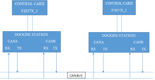
                      I am attaching the Block diagram of my present work on CAN communication between 2 control cards.

    So as I mentioned in my previous post, the source code in CCS Studio is successfully tested with two CAN ports (i.e CANA and CANB) of CONTROL CARD1 or with CONTROL CARD2, but the same operation is not getting executed with similar CAN PORTS (i.e CANA for CONTROL CARD1 and CANB for CONTROL CARD2. So I was asking you suggestions if similar problem has been faced by you for CAN data transmission.

    Regards

    Sumanta

  • Hi Sumanta,

    Thanks for providing the block diagram of your system. Sorry, maybe you have answered this question before but I still am not sure where the CAN transceivers are located. The F2837X Control Cards do not have built in CAN transceivers and the control card docking station (latest rev 4.1) does not have transceivers as well. Did you install CAN transceivers in your docking station or do you have custom docking station that has transceivers for each of the CAN modules?

    Regards,
    Joseph
  • Hi Joseph,

                       I have not specified regarding the CAN transceiver but in my system setup already Transceivers are fixed in separate PCBs which are connected to form the CAN Bus. So with similar architecture as mentioned in my previous post I have tested between 2 CAN PORTS of each CONTROL card and similar CAN PORTS each from individual CONTROL card where the problem in data transmission is observed. Please suggest.

    Regards

    Sumanta

  • Hi Sumanta,

    Ok, thank you for confirming your setup.  Do you have visibility on the CAN registers, specifically CAN_ES (Error and Status Register)?  Can you let me know what you read from this register on the transmitting node as well as with the receiving end?  This would tell us a lot about what is going on with your setup.

    Thanks and regards,

    Joseph

  • Hi Joseph,

                      Presently if 2 CAN ports of same control cards are accessed for data transmission, the informations observed in CAN register are as below:

    CAN_ES register: RxOk = 1 = TxOk, but if 2 CAN ports (1 from individual CONTROL cards) are utilised for data transmission,

    Bus-off state = Warning state = Error passive state = 1 and RxOk = 0 = TxOk, Last Error code = 010.

    Please suggest if some status information can be obtained from the above observations.

    Thanks in advance.

    Regards

    Sumanta 

  • Hi Joseph,

    I want to share some more informations regarding the status of CANA and CANB registers while performing the data transmission between 2 CAN ports:

    In CANa register:

    1) Last Error code (LEC) = 111, TxRqstReg1 = 01, Msg valid Register1 = 01, Access Data bytes (0-3) = 1,

    2) Access Data bytes (4-7) = 1, Transmit Interrupt Enable = 1, Transmit Request = 1, End of Block = 1,

    3) Data Length Code = 1000,

    4) CAN_IF1DATB and CAN_IF1DATA

    Data Byte 0 = 01111100,
    Data_1 = 10000001,
    Data_2 = 01111010,
    Data_3 = 10001010,
    Data_4 = 10000010,
    Data_5 = 10000010,
    Data_6 = 01110101,
    Data_7 = 10000001,

    In CANb register almost all parameters are having value of zero.

    Can you suggest some informations based on above parameters to find out the reason of not having proper data transmission between the CAN ports.

    Thanks in advance.


    Regards
    Sumanta
  • Hi Sumanta,

    Not sure if your issues have been resolved with ADC conversions and CAN data transmission.  Let me know if you still need some guidance.  I did not see any response based from Frank's feedback so I am just checking back with you.

    Regards,

    Joseph

  • Hi Sumanta,

    The bus-off state is a good indication why you cannot get data to transmit/receive via the CAN bus. You need to debug your application to see when the bus-off bit gets set. There is a feature in the CAN module that will allow the CAN to recover from bus-off state automatically. This feature is accomplished by setting the ABO bit in the CAN_CTL register (bit 9). Try setting this bit in your application code on both cards to see if this solves your problem.

    Regards,
    Joseph
  • Hi Sumanta,

    I think this post relates to the one I responded to earlier about the bus-off bit being set. There is more indication from this post that CANB is probably not initialized the fact that you are seeing values of 0 on the CANB registers. I am assuming the CANB is the module you are using on the second card and CANA if from the first card.

    On the second card, make sure that all these statements are executed:

    - GPIO mapping for CANB (make sure the correct GPIO channels are used and are actually connected to the transceiver)
    - CANInit(CANB_BASE); CANClkSourceSelect(CANB_BASE); CANBitRateSet(CANB_BASE, your_system_speed, your_baud_rate); CANIntEnable (for CANB if you decide to use interrupts when messages are received and of course add the interrupt definitions and ISRs)

    Once you have confirmed the above statements are executed on the second card, read back the CANB register values again and confirm if the registers still contain 0's. Do these steps first to ensure that CAN B on the 2ns card is indeed being configured correctly first.

    Regards,
    Joseph
  • Hi Joseph,

                      I have successfully tested the transmission of data from CAN A to CAN B and vice-versa through CAN_External_Transmit source

    codes. Now the next step is to build application for two separate MCU cards (i.e CANA from MCU1 and CANB from MCU2) with same source code.

    So it is becoming necessary to configure either CANA or CANB to act in Transmission mode and generating Interrupts with receiving of a particular

    message data. On debugging the 2 MCU cards with separate configuration applications, neither the CAN A or CAN B is able to receive data in

    receiving mode which I guess requires a proper configuration of the registers associated with CANA or CANB.

    Please suggest if it requires any other modifications in the source codes of CAN_External_Transmit

    Regards

    Sumanta