This thread has been locked.

If you have a related question, please click the "Ask a related question" button in the top right corner. The newly created question will be automatically linked to this question.

CCS/LAUNCHXL-F28379D: 2837x_rfft_adc_rt /FLASH_FASTRTS

Expert 1985 points
Part Number: LAUNCHXL-F28379D
Other Parts Discussed in Thread: CONTROLSUITE, C2000WARE

Tool/software: Code Composer Studio

Hello,

I am using the “2837x_rfft_adc_rt” examples provided by TI, the program is working fine and all the results(ADC input/fft values) are good when I build and load to the FLASH mode(Build Configurations -> Set Active -> Select FLASH_FASTRTS(…) ) using CCS, when board is connected to the CCS.

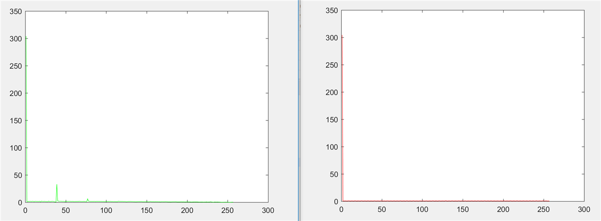
If I reconnect the board from my PC, program does not work completely (I can see the correct ADC input signal, but, FFTmagBuff[] does not work. In the other words, the Fourier transform seems to be taken, but its value is not correct and the results are wrong). The green graph(FFTmagBuff-correct result) is for the case where the launchpad is connected to the CCS and started to work by code composer studio. The red graph(results of FFTmagBuff are wrong) is for the case where the rest button of the board is pressed.

Thanks for your help.

Regards,

Amin

  • Hello,

    In this project, .cmd file is original file: F2837xD_FPU_RFFT_ADC_RT_lnk.cmd that provided by TI.

    How can I fix this problem?

    Regards,
    Amin

  • Amin,

    I am not sure when the issue occurs, If you are able to see the graphs CCS is connected,

    So the issue does not happen when you "load the code" and then run the code , correct?

    And if you halt, reset the device, restart and then "run" the code you are observing an error?

    How have you verified the ADC buffer is correct under both situations?
  • Hi Manish,

    I will send the data through the SCI UART port. Everything is correct when the device is disconnected from the CCS, except for Fourier results.

    Regards,
    Amin
  • Manish,

    In a simpler example, the frequency of the input signal is compared to a threshold,
    If the input frequency of signal is equal to threshold, GPIO=1, otherwise GPIO=0
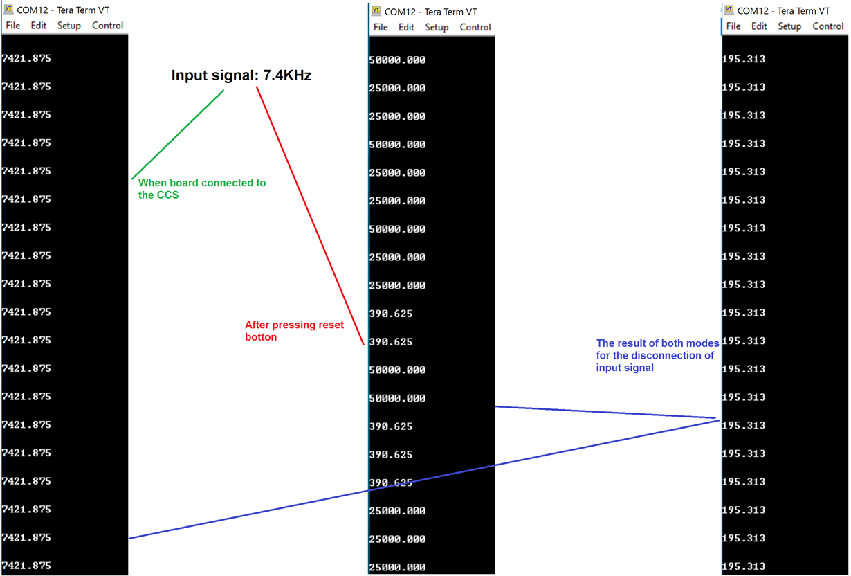
    In this example, when board is connected to CCS everything is right, but when the device is disconnected from the CCS (press reset button), this is not work.
    Thank you.

    Regards,
    Amin
  • Output results in different modes:


    Regards,
    Amin

  • Hi Manish,

    How can I fix this problem?
    Thank you.

    Regards,
    Amin
  • Hi,

    Is there anyone who can guide me?
    Thank you.

    Regards,
    Amin
  • Hi,

    Is there anyone who can guide me?
    Thank you.

    Regards,
    Amin
  • Amin,

    There is some confusion in the details that you provided.  When you say you disconnect CCS, I guess you mean you just click on CPU reset button in CCS.  Correct?  

    We need more clear info from you to be able to help you.  

    1) Did you change anything in the example code or linker command file?  

    2) Do you depend on any data in RAM that is not part of your executable file?  Make sure you copy all the required data from Flash to RAM in your application.

    3) Do you change any RAM content in the CCS memory window or watch window before or during the execution?

    4) Can you list down all the steps that you do in the passing and failing case?

    For example:

    1. Here is my boot mode pin configuration
    2. Then, I power up the board
    3. Connected to CCS
    4. Loaded the code to Flash
    5. Executed
    6. Then I clicked on CCS reset
    7. Then I clicked on CCS restart
    8. Control reached main and halted
    9. Then I clicked on resume button

    Thanks and regards,

    Vamsi

  • Hi Vamsi,

    Thanks for your reply.

    When you say you disconnect CCS, I guess you mean you just click on CPU reset button in CCS.  Correct? I reviewed various scenarios: reset button in CCS/ Mechanical reset button in board/Terminate

    1.Did you change anything in the example code or linker command file?  

    I reviewed various scenarios(Send data to SCI-A Uart - GPIO blinking to check frequency based on if/else). Finally, I am using the “2837x_rfft_adc_rt” examples provided by TI. 

    2) Do you depend on any data in RAM that is not part of your executable file? 

     I am using the “2837x_rfft_adc_rt” examples provided by TI.

    3) Do you change any RAM content in the CCS memory window or watch window before or during the execution? No

    4) Can you list down all the steps that you do in the passing and failing case?

    Please check this file, I am using the original “2837x_rfft_adc_rt” examples provided by TI.

    Rebuild project.pdf

    Best regards,

    Amin

  • Amin,

    What is the compiler version that you are using?
    Are you using the example from C2000Ware or from ControlSuite?

    In the linker command file that is provided in C2000Ware, I see that ramfuncs is not assigned to any memory.

    Thanks and regards,
    Vamsi
  • Hi Vamsi,

    compiler version: TI v16.9.4.LTS
    from ControlSuite

    F2837xD_FPU_RFFT_ADC_RT_lnk.cmd:

    //#############################################################################
    //
    // FILE:    F2837xD_FPU_RFFT_ADC_RT_lnk.cmd
    //
    // TITLE:   Linker Command File for FPU library examples that run 
    //          on the 2837x platform
    //
    //          This file includes all RAM and FLASH blocks present on the
    //          2837x and depending on the active build configuration(RAM or FLASH)
    //          the appropriate sections will either be loaded into RAM or FLASH 
    //          blocks
    //
    // Copyright (C) 2015 Texas Instruments Incorporated - http://www.ti.com/ 
    // ALL RIGHTS RESERVED 
    //#############################################################################
    // $TI Release: C28x Floating Point Unit Library V1.50.00.00 $
    // $Release Date: Jun 2, 2015 $
    //#############################################################################
    // NOTES:
    // 1. In addition to this memory linker command file, add the header linker 
    //    command file directly to the project. The header linker command file is 
    //    required to link the peripheral structures to the proper locations within
    //    the memory map.
    //    
    //    The header linker files are found in 
    //    controlSUITE\device_support\F2837x(D/S)\<version>\F2837x(D/S)_headers\cmd
    //    
    //    For BIOS applications add:      F2837x(D/S)_Headers_BIOS_cpuX.cmd
    //    For nonBIOS applications add:   F2837x(D/S)_Headers_nonBIOS_cpuX.cmd
    //
    // 2. On reset all RAMGSx blocks are under the mastership of CPU1. The user
    //     must configure the appropriate control registers to transfer mastership
    //     of a RAMGSx block over to CPU2
    //
    // 3. Memory blocks on F2837x are uniform (ie same physical memory) in both 
    //    PAGE 0 and PAGE 1. That is the same memory region should not be defined 
    //    for both PAGE 0 and PAGE 1. Doing so will result in corruption of program
    //    and/or data.
    //    
    //    Contiguous SARAM memory blocks can be combined if required to create a 
    //    larger memory block.
    //
    //#############################################################################
    
    // The following definitions will help to align the input buffer.For the complex FFT
    // of size N, the input buffer must be aligned to a 4N word boundary. For a real FFT
    // of size N, the input buffer must be aligned to a 2N word boundary. The user may define
    // the macro either in the linker command file, as shown here, or
    // through the project properties under,
    // C2000 Linker -> Advanced Options -> Command File Preprocessing -> --define
    --define RFFT_ALIGNMENT=1024
    #if !defined(RFFT_ALIGNMENT)
    #error define RFFT_ALIGNMENT under C2000 Linker -> Advanced Options -> Command File Preprocessing -> --define
    #endif
    
    MEMORY
    {
    PAGE 0 :
       /* BEGIN is used for the "boot to SARAM" bootloader mode   */
    #if defined(RAM)
       BEGIN           : origin = 0x000000, length = 0x000002
    #elif defined(FLASH)
       BEGIN           : origin = 0x080000, length = 0x000002
    #endif 
       RAMM0           : origin = 0x000122, length = 0x0002DE
       RAMM1           : origin = 0x000400, length = 0x000400
       
       RAMD0		   : origin = 0x00B000, length = 0x000800
       RAMD1		   : origin = 0x00B800, length = 0x000800
       
       RAMLS0          : origin = 0x008000, length = 0x000800
       RAMLS1          : origin = 0x008800, length = 0x000800
       RAMLS2          : origin = 0x009000, length = 0x000800
       
       RAMGS0		   : origin = 0x00C000, length = 0x001000
       RAMGS1		   : origin = 0x00D000, length = 0x001000
       RAMGS2		   : origin = 0x00E000, length = 0x001000
       RAMGS3		   : origin = 0x00F000, length = 0x001000
       
       RESET           : origin = 0x3FFFC0, length = 0x000002
       
       FLASHA           : origin = 0x080002, length = 0x001FFE	/* on-chip Flash */
       FLASHC           : origin = 0x084000, length = 0x002000	/* on-chip Flash */
       FLASHD           : origin = 0x086000, length = 0x002000	/* on-chip Flash */
       FLASHE           : origin = 0x088000, length = 0x008000	/* on-chip Flash */
       FLASHF           : origin = 0x090000, length = 0x008000	/* on-chip Flash */
       FLASHG           : origin = 0x098000, length = 0x008000	/* on-chip Flash */
       FLASHH           : origin = 0x0A0000, length = 0x008000	/* on-chip Flash */
       FLASHI           : origin = 0x0A8000, length = 0x008000	/* on-chip Flash */
       FLASHJ           : origin = 0x0B0000, length = 0x008000	/* on-chip Flash */
       FLASHK           : origin = 0x0B8000, length = 0x002000	/* on-chip Flash */
       FLASHL           : origin = 0x0BA000, length = 0x002000	/* on-chip Flash */
       FLASHM           : origin = 0x0BC000, length = 0x002000	/* on-chip Flash */
       FLASHN           : origin = 0x0BE000, length = 0x002000	/* on-chip Flash */   
    
    
    PAGE 1 :
       BOOT_RSVD       : origin = 0x000002, length = 0x000120     /* Part of M0, BOOT rom will use this for stack */
    
       RAMLS3          : origin = 0x009800, length = 0x000800
       RAMLS4          : origin = 0x00A000, length = 0x000800
       RAMLS5          : origin = 0x00A800, length = 0x000800
       
       RAMGS45		   : origin = 0x010000, length = 0x002000
       RAMGS67		   : origin = 0x012000, length = 0x002000
       RAMGS89		   : origin = 0x014000, length = 0x002000
       RAMGS1011	   : origin = 0x016000, length = 0x002000
    
       RAMGS12		   : origin = 0x018000, length = 0x001000
       RAMGS13		   : origin = 0x019000, length = 0x001000
       RAMGS14		   : origin = 0x01A000, length = 0x001000
       RAMGS15		   : origin = 0x01B000, length = 0x001000
    
       FLASHB          : origin = 0x082000, length = 0x002000	/* on-chip Flash */
    
    }
     
    SECTIONS
    {
       codestart        : > BEGIN,     PAGE = 0
    #if defined(RAM)
       ramfuncs         : > RAMM0,     PAGE = 0
       .text            :>> RAMM1 | RAMD0 | RAMD1 | RAMLS0,  PAGE = 0
       .cinit           : > RAMLS1,    PAGE = 0
       
       .pinit           : > RAMLS1,    PAGE = 0
       .switch          : > RAMLS1,    PAGE = 0
       .econst          : > RAMLS4,    PAGE = 1
    #elif defined(FLASH)
       ramfuncs         :  LOAD = FLASHC,
                           RUN = RAMLS1,
                           RUN_START(_RamfuncsRunStart),
                           LOAD_START(_RamfuncsLoadStart),
                           LOAD_SIZE(_RamfuncsLoadSize),
                           PAGE = 0
    
       .text            : > FLASHN,    PAGE = 0
       .cinit           : > FLASHM,    PAGE = 0
    
       .pinit           : > FLASHM,    PAGE = 0
       .switch          : > FLASHM,    PAGE = 0
       .econst          : > FLASHB,    PAGE = 1
    #else
    #error Add either "RAM" or "FLASH" to C2000 Linker -> Advanced Options -> Command File Preprocessing -> --define
    #endif //RAM
    
       /* Test specific sections */
       RFFTdata1        : > RAMGS45,   PAGE = 1, ALIGN = RFFT_ALIGNMENT
       RFFTdata2        : > RAMGS67,   PAGE = 1
       RFFTdata3        : > RAMGS89,   PAGE = 1
       RFFTdata4        : > RAMGS1011, PAGE = 1
       
       FPUmathTables    : > RAMGS12,   PAGE = 1
       
       .reset           : > RESET,     PAGE = 0, TYPE = DSECT /* not used, */
    
       .cio             : > RAMLS3,    PAGE = 1
       .sysmem          : > RAMLS3,    PAGE = 1
    
       .stack           : > RAMLS4,    PAGE = 1
       .ebss            : > RAMLS5,    PAGE = 1
       .esysmem         : > RAMLS4,    PAGE = 1
    }
    /*
    //===========================================================================
    // End of file.
    //===========================================================================
    */


    Thanks for your help.

    Regards,
    Amin
  • Amin,

    FPU_initFlash() function must be executed from RAM and not from Flash.  This function is not assigned to ramfuncs in the TI provided examples_setup.c file.  I attached the updated file here.  Try it.  Not sure if this change alone can fix the issue or not.  But this helps to configure the Flash wait-states correctly - hence, it may help.  Let me know.  Meanwhile, I will check with the author of the example to see if there are any other functions that should be executed from RAM to get correct results.  

    Thanks and regards,
    Vamsi

    examples_setup.c
    //#############################################################################
    //! \file  /examples/common/examples_setup.c
    //!
    //! \brief  Initialization routines for the FPU library examples
    //! \author Vishal Coelho
    //! \date   Feb 26, 2015
    //
    //  Group:             C2000
    //  Target Family:     F2837x
    //
    // Copyright (C) 2015 Texas Instruments Incorporated - http://www.ti.com/ 
    // ALL RIGHTS RESERVED 
    //#############################################################################
    //$TI Release: C28x Floating Point Unit Library V1.50.00.00 $
    //$Release Date: Jun 2, 2015 $
    //#############################################################################
    
    //*****************************************************************************
    // includes
    //*****************************************************************************
    #include "examples_setup.h"
    
    //*****************************************************************************
    // defines
    //*****************************************************************************
    
    //*****************************************************************************
    // globals
    //*****************************************************************************
    
    //*****************************************************************************
    // Function Prototypes
    //*****************************************************************************
    
    //*****************************************************************************
    // function definitions
    //*****************************************************************************
    
    void FPU_initSystemClocks()
    {
        InitSysCtrl();      //Enable peripheral clocks
    
        ClkCfgRegs.SYSCLKDIVSEL.bit.PLLSYSCLKDIV = 0x00;
    }
    
    void FPU_initEpie()
    {
        DINT;               //Globally disable maskable CPU interrupts
        InitPieCtrl();      //Clear and disable all PIE interrupts
        IER = 0x0000;       //Individually disable maskable CPU interrupts
        IFR = 0x0000;       //Clear all CPU interrupt flags
        InitPieVectTable(); //Populate PIE interrupt vector table with shell ISRs
    }
    
    #ifdef FLASH
    #pragma CODE_SECTION(FPU_initFlash,"ramfuncs");
    void FPU_initFlash()
    {
        EALLOW;
    
        //At reset bank and pump are in sleep
        //A Flash access will power up the bank and pump automatically
        //After a Flash access, bank and pump go to low power mode (configurable in
        //FBFALLBACK/FPAC1 registers)-
        //if there is no further access to flash
        //Power up Flash bank and pump and this also sets the fall back mode of 
        //flash and pump as active
        Flash0CtrlRegs.FPAC1.bit.PMPPWR = 0x1;
        Flash0CtrlRegs.FBFALLBACK.bit.BNKPWR0 = 0x3;
    
        //Disable Cache and prefetch mechanism before changing wait states
        Flash0CtrlRegs.FRD_INTF_CTRL.bit.DATA_CACHE_EN = 0;
        Flash0CtrlRegs.FRD_INTF_CTRL.bit.PREFETCH_EN = 0;
    
        //Set waitstates according to frequency
        //CAUTION
        //Minimum waitstates required for the flash operating
        //at a given CPU rate must be characterized by TI.
        //Refer to the datasheet for the latest information.
    #if CPU_FRQ_200MHZ
        Flash0CtrlRegs.FRDCNTL.bit.RWAIT = 0x3;
    #endif
    
    #if CPU_FRQ_150MHZ
        Flash0CtrlRegs.FRDCNTL.bit.RWAIT = 0x2;
    #endif
    
    #if CPU_FRQ_120MHZ
        Flash0CtrlRegs.FRDCNTL.bit.RWAIT = 0x2;
    #endif
    
        //Enable Cache and prefetch mechanism to improve performance
        //of code executed from Flash.
        Flash0CtrlRegs.FRD_INTF_CTRL.bit.DATA_CACHE_EN = 1;
        Flash0CtrlRegs.FRD_INTF_CTRL.bit.PREFETCH_EN = 1;
    
        //At reset, ECC is enabled
        //If it is disabled by application software and if application again wants 
        //to enable ECC
        Flash0EccRegs.ECC_ENABLE.bit.ENABLE = 0xA;
    
        EDIS;
    
        //Force a pipeline flush to ensure that the write to
        //the last register configured occurs before returning.
    
        __asm(" RPT #7 || NOP");
    }
    #endif //FLASH
    
    #ifdef ADCA
    void FPU_initADCA(void)
    {
        EALLOW;
        //write configurations
        AdcaRegs.ADCCTL2.bit.PRESCALE = 6; //set ADCCLK divider to /4
        AdcSetMode(ADC_ADCA, ADC_RESOLUTION_12BIT, ADC_SIGNALMODE_SINGLE);
    
        //Set pulse positions to early
        AdcaRegs.ADCCTL1.bit.INTPULSEPOS = 0;
    
        //power up the ADC
        AdcaRegs.ADCCTL1.bit.ADCPWDNZ = 1;
    
        //delay for 1ms to allow ADC time to power up
        DELAY_US(1000);
    
        //Select the channels to convert and end of conversion flag ADCA
        AdcaRegs.ADCSOC0CTL.bit.CHSEL     = 0;  //SOC0 will convert pin A0
        AdcaRegs.ADCSOC0CTL.bit.ACQPS     = 14; //sample window is 15 SYSCLK cycles
        AdcaRegs.ADCSOC0CTL.bit.TRIGSEL   = 5;  //trigger on ePWM1 SOCA/C
        AdcaRegs.ADCINTSEL1N2.bit.INT1SEL = 0;  //EOC0 is set to trigger ADCINT1
        AdcaRegs.ADCINTSEL1N2.bit.INT1E   = 1;  //enable INT1 flag
        AdcaRegs.ADCINTFLGCLR.bit.ADCINT1 = 1;  //make sure INT1 flag is cleared
        EDIS;
    }
    
    void FPU_initEPWM(void)
    {
        CpuSysRegs.PCLKCR2.bit.EPWM1             =1;  // Enable EPWM1 clocks
        CpuSysRegs.PCLKCR2.bit.EPWM2             =1;  // Enable EPWM1 clocks
        
        //Enable EPWM GPIOs
        InitEPwm1Gpio();
        InitEPwm2Gpio();
        
        EALLOW;
        // EPWM clock divider set to /2
        ClkCfgRegs.PERCLKDIVSEL.bit.EPWMCLKDIV = 1;                
        // Turn off the EPWM clock
        CpuSysRegs.PCLKCR0.bit.TBCLKSYNC       = 0;                
        // Disable SOC on A group
        EPwm1Regs.ETSEL.bit.SOCAEN             = 0;                
        // Select SOC on up-count
        EPwm1Regs.ETSEL.bit.SOCASEL            = 4;                
        // Generate pulse on 1st event
        EPwm1Regs.ETPS.bit.SOCAPRD             = 1;                
        // Set compare A value to 2000 counts
        EPwm1Regs.CMPA.bit.CMPA                = EPWM1_DUTY_CYCLE; 
        // Set period to 4000 counts
        EPwm1Regs.TBPRD                        = EPWM1_PERIOD;     
        // freeze counter
        EPwm1Regs.TBCTL.bit.CTRMODE            = 3;                
        //enable SOCA
        EPwm1Regs.ETSEL.bit.SOCAEN             = 1;                
        EPwm1Regs.TBCTL.bit.HSPCLKDIV          = EPWM_HSPCLKDIV;
        // Disable SOC on A group
        EPwm2Regs.ETSEL.bit.SOCAEN             = 0;                
        // Set compare A value to 10000 counts
        EPwm2Regs.CMPA.bit.CMPA                = EPWM2_DUTY_CYCLE; 
        // Set period to 20000 counts
        EPwm2Regs.TBPRD                        = EPWM2_PERIOD;     
        // freeze counter
        EPwm2Regs.TBCTL.bit.CTRMODE            = 3;                
        EPwm2Regs.TBCTL.bit.HSPCLKDIV          = EPWM_HSPCLKDIV;
        // Clear PWM1A on Zero
        EPwm1Regs.AQCTLA.bit.CAU               = AQ_SET;           
        EPwm1Regs.AQCTLA.bit.PRD               = AQ_CLEAR;         
        // Clear PWM2A on Zero
        EPwm2Regs.AQCTLA.bit.CAU               = AQ_SET;           
        EPwm2Regs.AQCTLA.bit.PRD               = AQ_CLEAR;
        
        EDIS;
    }
    
    void FPU_startEPWM(void)
    {
        // Turn on the EPWM
        EALLOW;
        CpuSysRegs.PCLKCR0.bit.TBCLKSYNC = 1;
        EPwm1Regs.TBCTL.bit.CTRMODE      = 0; //unfreeze, and enter up count mode
        EPwm2Regs.TBCTL.bit.CTRMODE      = 0; //unfreeze, and enter up count mode
        EDIS;
    }
    #endif //ADCA
    
    void done(void)
    {
        for(;;);
    }
    // End of file
    

  • Vamsi,

    Had no effect, It's like the past and the results are not right.
    Thank you.

    Best regards,
    Amin
  • Amin,

    Change the math tables definition to this

    FPUmathTables : LOAD = FLASHB,
    RUN = RAMGS12,
    RUN_START(_FPUmathTablesRunStart),
    LOAD_START(_FPUmathTablesLoadStart),
    LOAD_SIZE(_FPUmathTablesLoadSize),
    PAGE = 1

    In your code, you need to memcpy this section to its run location

    extern uint32_t FPUmathTablesRunStart, FPUmathTablesLoadStart, FPUmathTablesLoadSize;
    memcpy(&FPUmathTablesRunStart, &FPUmathTablesLoadStart, (uint32_t)&FPUmathTablesLoadSize);

    Since you are using the FASTRTS build the sin() and cos() routines used in the generation of the twiddle factors come from the FASTRTS library, which requires the tables in FPUmathTables. If you run with the JTAG connected CCS loads up the tables into RAM directly, whereas if you run in standalone - JTAG unplugged - you ought to load these tables in FLASH and then copy over to RAM at runtime.
  • Hi Vishal and Vamsi,

    Works well with this changes.
    Thanks for your helps.

    Best regards,
    Amin
  • Amin,

    Glad that it helped. Thanks for bringing this issue to our notice.
    We will correct the example so that others won't face this problem.

    Thanks and regards,
    Vamsi