This thread has been locked.

If you have a related question, please click the "Ask a related question" button in the top right corner. The newly created question will be automatically linked to this question.

i2c with Piccolo ControlStick via matlab / simulink

Other Parts Discussed in Thread: CCSTUDIO, TMS320F28335, ISO7241C

Hello folks,

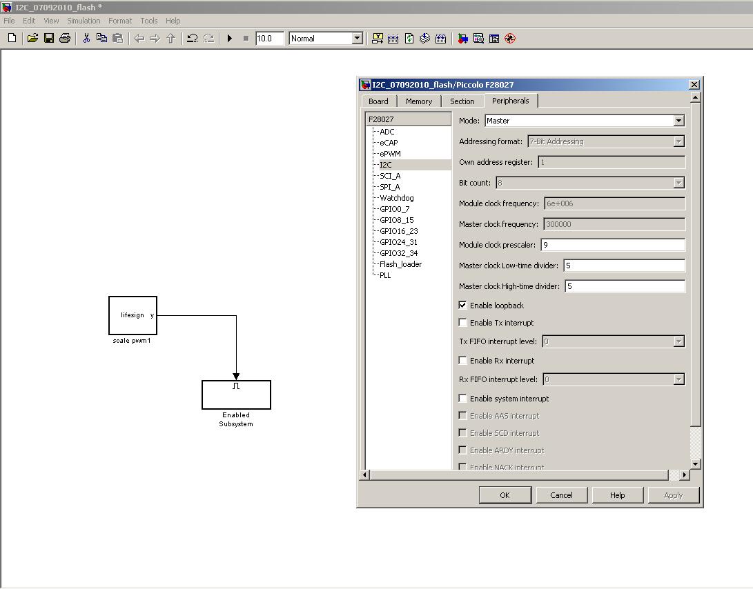
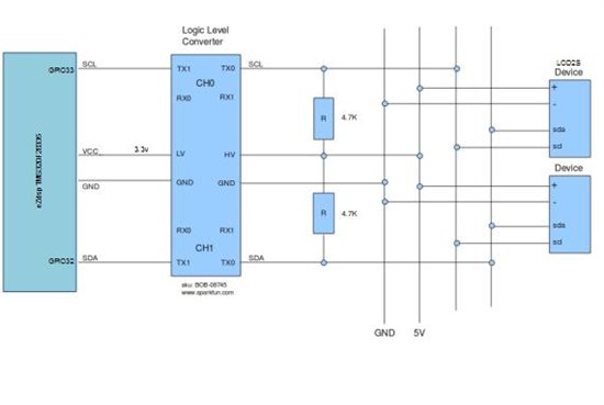
I'm trying to do i2c communication between two piccolo controlsticks programmed via matlab/simulink, but I didn't see any data on the SCL/SDA. First I setup one stick as master and sent some data, but there are no data on the SCL/SDA line. Then I tried to ad a slave to the master and do then the communication between them, but there are no data to see on the SCL/SDA line, too.

Have somebody experience with programming piccolo controlstick via simulink and can help me here?

Thank's in advance!!

Mihail

  • Hi Mihail,

    Let me ask some question:

    1) You use external pull up resistor for the i2c communication?

    2) What is the setup in the target preferences?

    You can use a loopback in the master, in this way you can check if the master is sending and receiving data.

    Regards

    Gastón

  •  

    Hi Gastón,

    to 1): no, I'm not using a pull-up resistor, but I tried with pull-up and it didn't function too.

    to 2):

    Thank You very much!

    Mihail

  • Mihail,

    Check the "Using the I2C Bus to Access a Connected EEPROM" in the target support package (Matlab help). See the configuration of the Bus. You can make a simple example:

    Use the I2C transmit, 2C receive , a constant block, switch, a GPIO block configured as toggle. 

    the diagram would be:   constant block------->i2c transmite               i2c receive----->switch----->>gpio

    transmite a constant, if the constant that you transmit is the same that you receive will trigger the gpio

    Using that model you can understand or check the Bus I2C, also read the i2c of the piccolo.

    I´m seeing in your model an "enable subsystem", this block will enable your subsystem only when the input is greater than zero, maybe this is your problem. Check the matlab help.

    I guess you must try a simple example, and then move to something difficult.

    Regards

    Gastón

  • At first thank You for the quickly reply!

    So, I saw already the example in the matlab help and did the settings as there.

    I tryed already and Your suggestion, but I can't see data on the SCL/SDA line.

    The trigger-box in my model is a s-function which give an 1 or 0 each second. I implement a SCI transmit block and it send data to the COM-port of the connected PC - the trigger source functions. 

    One thing, in the target settings I'm not able to set the speed of the i2c-module. Is this normal? Where can I do this? (10-400kbs: datasheet declaration)

    And another thing is, that the piccolo controlstick has double SCL/SDA pins, GPIO29,33/GPIO28,32. The GPIO33,32 are only carried out. The data sheet inform, that the GPIO33,32 are for the bootloader. Should I maybe cut the connection of GPIO29,28 to the FT 2232D and use them?

    Is necessary a slave connected to the master or I should see data when the master is trying to send data?

    I really didn't see any reason why the i2c-communication didn't work. Have You experience with the piccolo controlstick and simulink programming? Can You send me an simulink i2c-example?


    Thank's,

    Mihail

  • Mihail,

    Look at my files http://e2e.ti.com/members/1113552/files/default.aspx, there is an example model i made of i2c communication. You must do some configurations first:

    1) In Code Composer you must go to ------>Tools------>RTDX---->>configuration control------>configure

    select continuos mode

    click on enable RTDX to finish the configuration. Rigth click and select----->close

    2) Ctrl + B, and you will see the values comming on the RTDX block

    3) look for this program in your computer------>>>>gpdprog.exe

    That is a program from TI that enables you to see data in real time, i don´t remember but i guess is in the CCStudio_v3.3

    you must configure it, by puting the same name that appears on the model.

    Please check the configuration of the model

    Regards

    Gastón


  • Thank You, Gastón! You Are my Saver!!


    I already downloaded Your example and will test it tomorrow. Today I can't unfortunately test it.


    Have a nice day,

    Mihail

  •  

    Hello Gastón,

    I test Your example, it functions great. I thank Your very much for Your help! You are the BEST!!

    My last question is how can I setup the speed of the i2c-bus? Is this possible only through the PLL in the target setup? The module clock frequency is in my model masked and I can't set it.


    Best regards,

    Mihail

  • Mihail,

    Check this pdf http://focus.ti.com/lit/ug/sprufz9c/sprufz9c.pdf, it will help you to understand this protocol also to configure the registers.

    In this link, you will find some PDF´s that you must read to Know  better the processor you have http://focus.ti.com/docs/prod/folders/print/tms320f28027.html.

    Regards

    Gastón

  • Hi Mihail,

    Check the I2C Receive block in simulink, double click on it and you'll see  the dialog box------>>>>check the slave address source ----->>choose  input port. That will have to solve your problems.

    Best regards

    Gastón

  •  

    Hi Gaston,

    I tested Your suggestion but it didn't work. Can You please see my matlab/simulink models for master and slave at my files? Do You find some mistakes?


    Thanks,

    Mihail

  • Hi Mihail, sorry for the delay but i´m very busy. Please send me your model and I will check it soon. 

    Search for this info on the web, also to read the matlab help ( yes .....again).

    Regards

    Gastón

  • Hi Gaston, i ve seen seen your post and i think that you have vast experience i2c in simulink with target support packge, these days, i have a problem with

    this. i hope you can give a clue to solve the problem. i have a eZdsp TMS320F28335 board connectted to the LCD2S throught I2C. Between these two components, i put a logic level  converter (BOB-08745 ) due to that both have different voltage levels. i made a program in simulink with (target support package toolbox) to control the LCD and in this program i send two bytes one to configure the LCd and the second to to clear the LCD because in the lcd  appears the following msn "this is a 4x20 line lcd display....www.modtrotrix". when i turn it on. 

    i set the model in looback, i saw the the two bytes throught RTDX, after that i connected the lcd with the microcontroller and nothing happens, i saw the same msn and i could not erase the msn from the LCD. the picture below show the connection which i have made

    The picture was modified and retrieved from sparkfun forum.

    the next picture show the simulink model which i did.

    i thought this problem was related to timing but when i try to change the i2c module and master clock frecuency including (module prescaler, master clock low time divider and high divider) in targert preferences but a msn apperes assertion failed so simulink did not allow me to change this parameters.

    could you help with any clue?

    regard,

    david

  • Did you check the signals level in the high side of the LCD?

    You could connect the tx and rx lines of the level converter to check if the communications is ok in the high side of your board.

    I see the level converter as already resistor (10K) http://www.sparkfun.com/datasheets/BreakoutBoards/Level-Converter-v10.pdf 

    link for the lcd datasheet?

    Gastón

  • Hi Gaston, thanks for your time,

    i check the signals, i saw the clock signal in both sides, one side much biguer than the other. howerver i could not detect SDA line.  what do you mean in the connection

    between tx and rx? you mean should i connect for example sda to txi - txo and txo to rxi and see the signal from rxi with the oscilloscope. i think the

    10k resistors are already incorporated into the converter.

    i am using this LCD 8053.lcd2sr1_v140.pdf8156.lcd204a-yha.pdf

    can this problem related to clock mismatch?

    regards,

    david

  • If you do a loopback in the high side of the circuit (5V) you should recive the data in the rtdx (matlab). By doing this, you check if the signals are OK just before reach the lcd. 

    can this problem related to clock mismatch? yes, in that case you'll need to check the lcd datasheet and set the frecuency of the i2c. check the target prefernces of your dsc.

    Si entedes esto hablas español y no hay drama que me realices preguntas de esa manera.

    A couple of things:

    1) You should read the lcd datasheet first to be able to do proper configurations of the dsc (clock frecuency among others).

    2) Check the matlab help for simulink examples.

    3) You could use the iso7241 instead the level converter. (check datasheet)

    hope this help.

    Gastón

  • let see first the clock mismatch:

    have a look, i wrote '14'  in the module clock preescaler and suddenly this error came up 'assersion failed'. i thik that i know how to calculate the I2c frecuency

    I2C module clock=sysclkout/(IPSC +1) =150Mhz/(14+1)=10MHZ

    I2c master clock of 50khz so Tmaster=(IPSC+1)[(ICCL+d)+(ICCH+d)]  / (sysclkout)

    Tmaster=1/50khz=20microse

    IPSC=14 , d= 5

    so if we sustitute all variable, we obtain ICCL+ICCH=190,

    to have duty cycle of 50%,

    IPSC=14, ICCL=95,ICCH=95 (IPSC module precaler, ICCL low time divider, ICCH high time divider)

    if i put these parameters in the this window, this error came up.

    si hablo español,  si compro el iso7241, me tocaria comprarle el socket para poner  este intergrado, dudas que el que el sparkfun logic converter funcione?

    si te soy sincero, no se como puedo haver el loopback fisicamente, lo puedo hacer en sofware.. tengo que puentiar el txo a la entrada del rxi y luego connectarsela al pin del SDA?

    me imaginoque tu debes ser argentino? soy colombiano..

    no hay lio por hablar español...? anyway gracias por tu ayuda,

  • Si no configuras el clock del dsc con el del lcd no te va a funcionar porque seria similar a comunicarse con otra persona a destiempo. Te recomiendo que empleando algún ejemplo  de i2c fijes una frecuencia (necesitada por el lcd) y lo comprubes con tu osciloscopio ( antes y despues del cambiador de nivel - de esta forma determinas si tu problema es el cambiador de nivel- lo cual dudo). Ten en cuentra que tendras algun error debido a los retardos presentes en el mosfet.

    dame el link del lcd (no descargo pdf's)

    Te dije lo del iso7241c porque esta preparado para comunicaciones de alta velocidad. Supuse que lo soldas directo a la placa para hacer el testeo de tu soft. Si no es así te recomiendo usar optoacopladores.

    Read the i2c module of the dsc to do a proper config. 

    Use the scope to check the frecuency of the i2c com, I say iso7241 because is prepare for high speed communications and you can use it in the testing board instead using wires and different modules. You can use optocouplers as well.

    Gastón

  • gracias, por tu ayuda estos son los archicos de la LCD

    6735.lcd2sr1_v140.pdf0045.lcd204a-yha.pdf

    lo de los configuracion del target, no tengo que re leer por que yo pense que lo habia entendido..

  • Hi, i have the same problem, im using the same target and i cant see the clock signal or something in the SCL/SDA pins, can you send me the example? thanks... or contact with me to alfregomezdelga@hotmail.com
  • Would you mind sharing this file on Mathworks File Exchange?