Other Parts Discussed in Thread: CONTROLSUITE, HALCOGEN, SN65HVD234, ISO1050
Hello,
I am using LAUNCHXL28069M KIT along with my development board having TMS570LS4x micro controller for CANBus communication.
LAUNCHXL28069M as receiver side and TMS570LS4x as a transmitter side CAN..
For LAUNCHXL28069M receiver side i am referring C:\ti\controlSUITE_3.4.5\device_support\f2806x\v151\F2806x_examples_ccsv5\ecan_back2back sample code
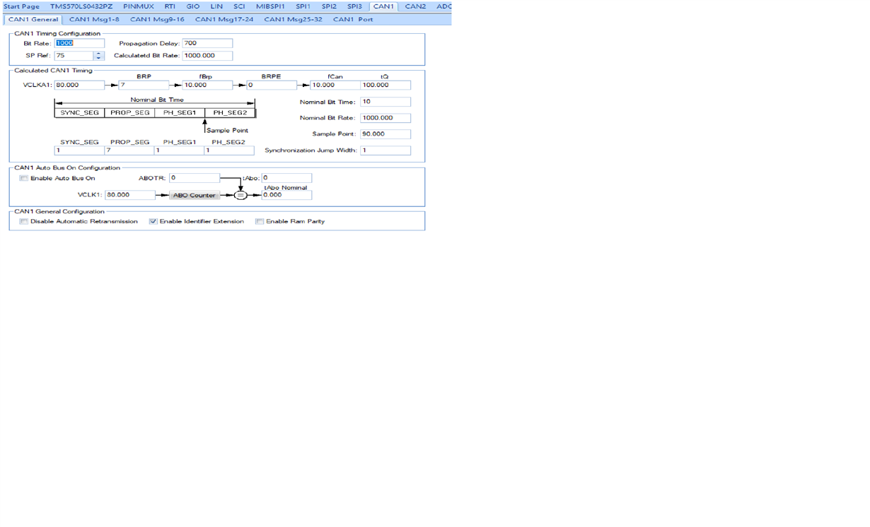
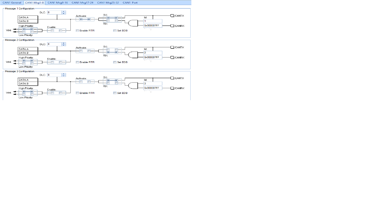
and for TMS570LS4x Tx CAN side C:\ti\Hercules\HALCoGen\v04.06.01\examples\TMS570LS04x_03x_02x/example_Can_communication. i have created caninit function using HALCogen tool.
after this configuration i am not receiving valid data on Rx CAN side every time receiving data which in not my actual transmitted data . please suggest me if i am wrong in CAN bus initialization function.below is my code for both Tx and Rx side.
Is there any issue with endiness...? or signal CaNH and CANL because on LAUNCHXL28069M sn65hvd234 CAN transceiver IC used which is not having 5 volt Vcc on secondary side and on my development board i am using ISO1050 CAN transceiver which is 5 volt Vcc2.
>>>>>>>>>>>>>>>>>>>>> CAN RX code >>>>>>>>>>>>>>>>>>>>>>>>>>>>>>>>>>>>>>
LAUNCHXL28069M receiver side CAN code
InitECana();//CAn init function from
EALLOW;
ECanaMboxes.MBOX16.MSGID.all = 0x00000001;
EDIS;
ECanaRegs.CANMD.all = 0xFFFF0000;
ECanaRegs.CANME.all = 0xFFFFFFFF;
EALLOW;
ECanaRegs.CANMIM.all = 0xFFFFFFFF;
EDIS;
EALLOW;
ECanaShadow.CANMC.all = ECanaRegs.CANMC.all;
ECanaShadow.CANMC.bit.STM = 0; // Configure CAN for self-test mode 1
ECanaRegs.CANMC.all = ECanaShadow.CANMC.all;
EDIS;
for(;;)
{ for(j=16; j<32; j++) // Read & check 16 mailboxes
{
mailbox_read(j); // This func reads the indicated mailbox data
mailbox_check(TestMbox1,TestMbox2,TestMbox3); // Checks the received data
//mailbox_read(16);
}
}End of main function****************************
void InitECana(void) // Initialize eCAN-A module
{
struct ECAN_REGS ECanaShadow;
EALLOW; // asm(" asm(" EALLOW")") enables access to protected bits
/* Configure eCAN RX and TX pins for CAN operation using eCAN regs*/
ECanaShadow.CANTIOC.all = ECanaRegs.CANTIOC.all;
ECanaShadow.CANTIOC.bit.TXFUNC = 1;
ECanaRegs.CANTIOC.all = ECanaShadow.CANTIOC.all;
ECanaShadow.CANRIOC.all = ECanaRegs.CANRIOC.all;
ECanaShadow.CANRIOC.bit.RXFUNC = 1;
ECanaRegs.CANRIOC.all = ECanaShadow.CANRIOC.all;
/* Configure eCAN for HECC mode - (reqd to access mailboxes 16 thru 31) */
// HECC mode also enables time-stamping feature
ECanaShadow.CANMC.all = ECanaRegs.CANMC.all;
ECanaShadow.CANMC.bit.SCB = 1;
ECanaRegs.CANMC.all = ECanaShadow.CANMC.all;
/* Initialize all bits of 'Message Control Register' to zero */
// Some bits of MSGCTRL register come up in an unknown state. For proper operation,
// all bits (including reserved bits) of MSGCTRL must be initialized to zero
ECanaMboxes.MBOX0.MSGCTRL.all = 0x00000000;
ECanaMboxes.MBOX1.MSGCTRL.all = 0x00000000;
ECanaMboxes.MBOX2.MSGCTRL.all = 0x00000000;
ECanaMboxes.MBOX3.MSGCTRL.all = 0x00000000;
ECanaMboxes.MBOX4.MSGCTRL.all = 0x00000000;
ECanaMboxes.MBOX5.MSGCTRL.all = 0x00000000;
ECanaMboxes.MBOX6.MSGCTRL.all = 0x00000000;
ECanaMboxes.MBOX7.MSGCTRL.all = 0x00000000;
ECanaMboxes.MBOX8.MSGCTRL.all = 0x00000000;
ECanaMboxes.MBOX9.MSGCTRL.all = 0x00000000;
ECanaMboxes.MBOX10.MSGCTRL.all = 0x00000000;
ECanaMboxes.MBOX11.MSGCTRL.all = 0x00000000;
ECanaMboxes.MBOX12.MSGCTRL.all = 0x00000000;
ECanaMboxes.MBOX13.MSGCTRL.all = 0x00000000;
ECanaMboxes.MBOX14.MSGCTRL.all = 0x00000000;
ECanaMboxes.MBOX15.MSGCTRL.all = 0x00000000;
ECanaMboxes.MBOX16.MSGCTRL.all = 0x00000000;
ECanaMboxes.MBOX17.MSGCTRL.all = 0x00000000;
ECanaMboxes.MBOX18.MSGCTRL.all = 0x00000000;
ECanaMboxes.MBOX19.MSGCTRL.all = 0x00000000;
ECanaMboxes.MBOX20.MSGCTRL.all = 0x00000000;
ECanaMboxes.MBOX21.MSGCTRL.all = 0x00000000;
ECanaMboxes.MBOX22.MSGCTRL.all = 0x00000000;
ECanaMboxes.MBOX23.MSGCTRL.all = 0x00000000;
ECanaMboxes.MBOX24.MSGCTRL.all = 0x00000000;
ECanaMboxes.MBOX25.MSGCTRL.all = 0x00000000;
ECanaMboxes.MBOX26.MSGCTRL.all = 0x00000000;
ECanaMboxes.MBOX27.MSGCTRL.all = 0x00000000;
ECanaMboxes.MBOX28.MSGCTRL.all = 0x00000000;
ECanaMboxes.MBOX29.MSGCTRL.all = 0x00000000;
ECanaMboxes.MBOX30.MSGCTRL.all = 0x00000000;
ECanaMboxes.MBOX31.MSGCTRL.all = 0x00000000;
// TAn, RMPn, GIFn bits are all zero upon reset and are cleared again
// as a matter of precaution.
ECanaRegs.CANTA.all = 0xFFFFFFFF; /* Clear all TAn bits */
ECanaRegs.CANRMP.all = 0xFFFFFFFF; /* Clear all RMPn bits */
ECanaRegs.CANGIF0.all = 0xFFFFFFFF; /* Clear all interrupt flag bits */
ECanaRegs.CANGIF1.all = 0xFFFFFFFF;
/* Configure bit timing parameters for eCANA*/
ECanaShadow.CANMC.all = ECanaRegs.CANMC.all;
ECanaShadow.CANMC.bit.CCR = 1 ; // Set CCR = 1
ECanaRegs.CANMC.all = ECanaShadow.CANMC.all;
// Wait until the CPU has been granted permission to change the configuration registers
do
{
ECanaShadow.CANES.all = ECanaRegs.CANES.all;
} while(ECanaShadow.CANES.bit.CCE != 1 ); // Wait for CCE bit to be set..
ECanaShadow.CANBTC.all = 0;
ECanaShadow.CANBTC.all =0x000203BD;//0x000503BD= 500k;;0x000203BD;=1Mbps sysclock 90MHz
ECanaRegs.CANBTC.all = ECanaShadow.CANBTC.all;
ECanaShadow.CANMC.all = ECanaRegs.CANMC.all;
ECanaShadow.CANMC.bit.CCR = 0 ; // Set CCR = 0
ECanaRegs.CANMC.all = ECanaShadow.CANMC.all;
// Wait until the CPU no longer has permission to change the configuration registers
do
{
ECanaShadow.CANES.all = ECanaRegs.CANES.all;
} while(ECanaShadow.CANES.bit.CCE != 0 ); // Wait for CCE bit to be cleared..
/* Disable all Mailboxes */
ECanaRegs.CANME.all = 0; // Required before writing the MSGIDs
EDIS;
}
>>>>>>>>>>>>>>>>>> END of Rx code>>>>>>>>>>>>>>>>>>>>>>>>>>>>>>>>>>
<<<<<<<<<<<<<<<<<CAN Tx code TMS570LS4x <<<<<<<<<<<<<<<<<<<<<<<<<<<<
canInit();
uint8 can_data[1]={0xAA};
while(1)
{
canTransmit(canREG1, canMESSAGE_BOX1, &can_data[0]);
memset(rx_data,0,sizeof(rx_data));
wait(0xFFF);
}*****************End of main function*******************
void canInit(void)
{
/** - Setup control register
* - Disable automatic wakeup on bus activity
* - Local power down mode disabled
* - Disable DMA request lines
* - Enable global Interrupt Line 0 and 1
* - Disable debug mode
* - Release from software reset
* - Enable/Disable parity or ECC
* - Enable/Disable auto bus on timer
* - Setup message completion before entering debug state
* - Setup normal operation mode
* - Request write access to the configuration registers
* - Setup automatic retransmission of messages
* - Disable error interrupts
* - Disable status interrupts
* - Enter initialization mode
*/
canREG1->CTL = (uint32)0x00000000U
| (uint32)0x00000000U
| (uint32)((uint32)0x00000005U << 10U)
| (uint32)0x00020043U;
/** - Clear all pending error flags and reset current status */
canREG1->ES |= 0xFFFFFFFFU;
/** - Assign interrupt level for messages */
canREG1->INTMUXx[0U] = (uint32)0x00000000U
| (uint32)0x00000000U
| (uint32)0x00000000U
| (uint32)0x00000000U
| (uint32)0x00000000U
| (uint32)0x00000000U
| (uint32)0x00000000U
| (uint32)0x00000000U
| (uint32)0x00000000U
| (uint32)0x00000000U
| (uint32)0x00000000U
| (uint32)0x00000000U
| (uint32)0x00000000U
| (uint32)0x00000000U
| (uint32)0x00000000U
| (uint32)0x00000000U
| (uint32)0x00000000U
| (uint32)0x00000000U
| (uint32)0x00000000U
| (uint32)0x00000000U
| (uint32)0x00000000U
| (uint32)0x00000000U
| (uint32)0x00000000U
| (uint32)0x00000000U
| (uint32)0x00000000U
| (uint32)0x00000000U
| (uint32)0x00000000U
| (uint32)0x00000000U
| (uint32)0x00000000U
| (uint32)0x00000000U
| (uint32)0x00000000U
| (uint32)0x00000000U;
/** - Setup auto bus on timer period */
canREG1->ABOTR = (uint32)0U;
/** - Initialize message 1
* - Wait until IF1 is ready for use
* - Set message mask
* - Set message control word
* - Set message arbitration
* - Set IF1 control byte
* - Set IF1 message number
*/
/*SAFETYMCUSW 28 D MR:NA <APPROVED> "Potentially infinite loop found - Hardware Status check for execution sequence" */
while ((canREG1->IF1STAT & 0x80U) ==0x80U)
{
} /* Wait */
canREG1->IF1MSK = 0xC0000000U | (uint32)((uint32)((uint32)0x00007FFU & (uint32)0x1FFFFFFFU) << (uint32)0U);
canREG1->IF1ARB = (uint32)0x80000000U | (uint32)0x40000000U | (uint32)0x20000000U | (uint32)((uint32)((uint32)1U & (uint32)0x1FFFFFFFU) << (uint32)0U);
canREG1->IF1MCTL = 0x00001000U | (uint32)0x00000000U | (uint32)0x00000000U | (uint32)0x00000000U | (uint32)8U;
canREG1->IF1CMD = (uint8) 0xF8U;
canREG1->IF1NO = 1U;
/** - Setup IF1 for data transmission
* - Wait until IF1 is ready for use
* - Set IF1 control byte
*/
/*SAFETYMCUSW 28 D MR:NA <APPROVED> "Potentially infinite loop found - Hardware Status check for execution sequence" */
while ((canREG1->IF1STAT & 0x80U) ==0x80U)
{
} /* Wait */
canREG1->IF1CMD = 0x87U;
/** - Setup IF2 for reading data
* - Wait until IF1 is ready for use
* - Set IF1 control byte
*/
/*SAFETYMCUSW 28 D MR:NA <APPROVED> "Potentially infinite loop found - Hardware Status check for execution sequence" */
while ((canREG1->IF2STAT & 0x80U) ==0x80U)
{
} /* Wait */
canREG1->IF2CMD = 0x17U;
/** - Setup bit timing
* - Setup baud rate prescaler extension
* - Setup TSeg2
* - Setup TSeg1
* - Setup sample jump width
* - Setup baud rate prescaler
*/
canREG1->BTR = (uint32)((uint32)0U << 16U) |
(uint32)((uint32)(1U - 1U) << 12U) |
(uint32)((uint32)((7U + 1U) - 1U) << 8U) |
(uint32)((uint32)(1U - 1U) << 6U) |
(uint32)7U;
/** - CAN1 Port output values */
canREG1->TIOC = (uint32)((uint32)1U << 18U )
| (uint32)((uint32)0U << 17U )
| (uint32)((uint32)0U << 16U )
| (uint32)((uint32)1U << 3U )
| (uint32)((uint32)1U << 2U )
| (uint32)((uint32)1U << 1U );
canREG1->RIOC = (uint32)((uint32)1U << 18U )
| (uint32)((uint32)0U << 17U )
| (uint32)((uint32)0U << 16U )
| (uint32)((uint32)1U << 3U )
| (uint32)((uint32)0U << 2U )
| (uint32)((uint32)0U <<1U );
/** - Leave configuration and initialization mode */
canREG1->CTL &= ~(uint32)(0x00000041U);
}
Thanks in advance..


