This thread has been locked.

If you have a related question, please click the "Ask a related question" button in the top right corner. The newly created question will be automatically linked to this question.

TIDM-DELFINO-ETHERCAT: Using Distributed Clock in EtherCAT network.

Part Number: TIDM-DELFINO-ETHERCAT
Other Parts Discussed in Thread: LAUNCHXL-F28379D, , CONTROLSUITE, TMDSECATCNCD379D, TMDSICE3359

Hello,

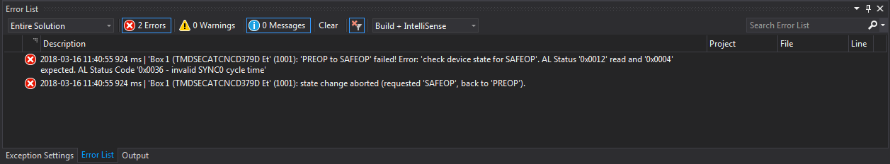
I successfully ran TIDM-DELFINO-ETHERCAT connected to LaunchXL-F28379D. I have an access to ETG so I could prepare stack files, assign Vendor ID and connect to TwinCAT 3. And it runs in Free Run cycle. And here is my issue - free run cycle works with 4ms cycle. I have to decrease this time to about 100 us. I think that Distributed Clock (DC) is necessary here but I have no idea how to setup it correctly. Every single change in TwinCAT related to DC mode breaks transmission.

My question - how should I turn Distributed Clock on? In my SSC files DC_SUPPORTED and AL_EVENT_ENABLED are set to 1 so it is possible to use DC mode I presume.

BR,

Dawid.

  • Dawid,
    so now you have the HAL for LaunchXL prepared. Did you check the C28x SSC port/patch files provided in controlSuite for TMDSECATCNCD379D kit?

    You can generate the SSC files using the patches and replace the HAL with your code. The patches will have DCx enabled and also compare your HAL with TI provided HAL for TMDSECATCNCD379D kit, for if you have the needed GPIO and ISR initializations for SYNC0/1 in your HAL or not.

    You will have to then go enable DCx from the master and reload the slave devices and you should see the SYNC ISR happening. What is the error you see on master when you turn on DCx?

    Best Regards
    Santosh Athuru
  • Santosh,

    I did what you wrote. I generated SSC with patch provided in controlSuite for TMDSECATCNCD379D kit. I made some changes in defines to apply to launchxl-f28379d pins. And it is running, we were fighting with that in another thread and we did it successfully :)

    But when I set DC mode in TwinCAT and then I am trying to send command like switch LED then I can't see any change in CCS debugger. Do I have to do something more to turn DC mode on?

    BR,
    Dawid.

  • Santosh,

    I successfully ran DC mode - thanks to you :) You wrote that I should RELOAD DEVICES. I didn't do it before...

    Now I am able to set cycle time to 500 us. Free run cycle is set to 1ms but in Advanced Settings I defined Sync 0 Cycle Time to 500 us.

    My target is about 100 us but when I set time below 500 us, e.g. 400 us I can see "Synchronization error" in error list. Should I do something with shift times or Sync1?

    I appreciate your help Santosh.

    BR,
    Dawid.

  • Dawid,

    you don't have to necessarily do that, both SYNC0 and SYNC1 can be configured independent as needed, only thing you need to make sure is how the ISRs are handled in SW, while CPU is handling one ISR the second triggered one has to wait till first is serviced by default. Try disabling SYNC1 and see if it helps your experiments.

    I'm not sure about the synchronization error you are talking about. Which PDI you are using ASYNC16 or SPI? There could be a limit to how low you can go with the SYNC time, with ASYNC16 the timing should be far better than SPI.

    Hope this helps.

    Best Regards

    Santosh Athuru

  • Santosh,

    sorry for late response, but today I am able to check this out in lab.
    I am using ASYNC16. As you said, I disabled SYNC1 and I used only SYNC0. And still got the same. When SYNC0 is set with 500 us cycle it's still working but when I decrease it to e.g. 400 us I can see that error:

    After that error RUN led on TIDM-DELFINO-ETHERCAT is blinking.

    And it is my opinion too that ASYNC16 should has better timing limit that SPI.

    What do you think about that?  Should I do something with shift time or there are another settings?

    BR,
    Dawid.

  • Dawid,
    can you check the clock cycles for the whole SYNC 0 ISR? Put a break point at the entry and exit of ISR and count clock cycles taken between break points. Please look at steps to enable count event in the below link, once you have the clock cycles then you know how long the ISR is taking with CPU running at 200MHz. This should give us some idea on what can be done next.

    processors.wiki.ti.com/.../Hardware_Breakpoints_and_Watchpoints_for_C28x_in_CCS

    Best Regards
    Santosh Athuru
  • Santosh,

    I did exactly what you wrote. I measured cycles within ISR and between them. Here are my screenshots:

    Here is my SysPll config:

    InitSysPll(XTAL_OSC,IMULT_40,FMULT_0,PLLCLK_BY_2);

    I changed it from:

    InitSysPll(/*INT_OSC2*/XTAL_OSC,IMULT_20,FMULT_0,PLLCLK_BY_1);

    It seems that ISR is quite fast. What do you think about that?

    BR,
    Dawid.

  • Santosh,

    I would like to provide you more information. Before you wrote how to check cycles in debug I was checking some time ranges by using timers. And I checked how often void APPL_Application(void); function is firening.
    So:

    1) in TwinCAT I set DC-mode with 600 us cycle time.
    2) in main function I set timer 1 like that: CpuTimer1Regs.TPR.bit.TDDR = 199; so with 200 MHz clock 1 tick lasts 1 us.
    3) in APPL_Application function I added that code at the beginning:

    time = 0xFFFFFFFF - CpuTimer1Regs.TIM.all;
    CpuTimer1Regs.TCR.bit.TSS = 1;     // 1 = Stop timer, 0 = Start/Restart Timer
    CpuTimer1Regs.TCR.bit.TRB = 1;     // 1 = reload timer
    CpuTimer1Regs.TCR.bit.TSS = 0;     // 1 = Stop timer, 0 = Start/Restart Timer

    4) in Watch Expressions I added variable 'time'
    5) load application and reload devices in TwinCAT.

    As I said, cycle time is set to 600 us and while application running 'time' variable is about 600. Everything looks correct. Here is screen from watch expressions:

    Next I checked cycles just like I checked cycles in ISR Sync0. I put breakpoints at the beginning and at the and of APPL_Application function. So, from beginning to the end APPL_Application function lasts about 77 cycles:

    I checked time from returning of APPL_Application to next fireing this function and this is about 2720 cycles:

    But at the same time, value of 'time' variable which was used to save measured time from timer decreased from 600 to 17! I have no idea why.

    I thought it should be about 600 still. What do you think about this behaviour?

    BR,
    Dawid.

  • Santosh,

    let's forget for a while about my previous questions. I would like ask you another very importan question.

    I connected my Launchpad to another EtherCAT master based on AM335 sitara uP, it's TMDSICE3359 board from TI. In this master I increment processing value in each cycle, it's DataFromMaster register. In slave application on Launchpad in void APPL_Application(void) I wanted to save data in register, I mean sth like this:

    void APPL_Application(void)
    {
            register[i] = DatafromMaster0x7010.DatafromMaster;
            i++;
            //... another procedures
    }

    In watch expressions I can see that DatafromMaster register is incrementing fine, but in register array I can see that all register[i] values are equal to current Datafrommaster! I mean, it looks like APPL_Application functions fires much more faster than EtherCAT frame cycle. I thought APPL_Application fires each cycle time, e.g. 1ms or 500 us, generally depends on master.

    Situation I described looks like this:

    DatafromMaster = 0x01;

    register[0] = 0x01, register[1] = 0x01, register[2] = 0x01, ... , register[n-1] = 0x01;

    ---sending frame, cycle time elapsed---

    DatafromMaster = 0x02;

    register[0] = 0x02, register[1] = 0x02, register[2] = 0x02, ... , register[n-1] = 0x02;

    I thought it should be:

    DatafromMaster = 0xFF;

    register[0] = 0, register[1] = 0x01, ... , register[0xFE] = 0xFF.


    What do you think about that?

    BR,
    Dawid.

  • Dawid,
    I haven't had time to look at the DC usage questions from one post above, but as you suggest we will get back to them after we debug your latest question above about the APPL_Application() firing.

    The outputs are updated from the (ESC memory to local RAM) in the PDO_OutputMapping() function called from PDI_ISR or SYNC0_ISR or MainLoop. Whenever master changes the output variable a frame is sent to the ESC to have the outputs updated in the SM buffer. Now if the corresponding SM Event is enabled to generate the PDI IRQ interrupt then PDI ISR triggers and outputs are updated. This will cause the DatafromMaster to get updated with the value in SM buffer (=master sent a frame to get this updated in SM buffer).

    Now based on above logic and based on what I see in ET9300 SSC documentation, it shouldn;t be possible for APPL_Application to run more frequent than the SM2 Event occurrence. Now if your slave stack code is dropping off of OP mode and getting back to OP Mode then you might see this error and looking at the MainLoop(), ECAT_Application() can be called when interrupts are not enabled yet and DC Sync is not active yet.

    With the AM335x master, is there anyway you could see if the Slave node is falling off of OP Mode, I know TWINCAT can show the errors. Or you could put a break point in the OP->SAFEOP mode transition functions in slave stack and see if this is happening or put a break point or counter variable in the ECAT_Application() call from the MainLoop() and see if this is happening.

    Good questions :-)

    Hope this helps.

    Best Regards
    Santosh Athuru
  • Santosh,

    I think I am close to resolve my issue. When I opened SSC Tool and I loaded C28x project with stack options I found out that parameter MIN_PD_CYCLE_TIME is set on 0x7A120 which is... 500 us! And this is my lowest sync0 time I can make communication correct! I think that next step I should make is to change that parameter in SSC and export ESI file.
    But here is one more thing I have to ask. In SmartView in TwinCAT when I upload EEPROM with ESI file TI provided I can see in SYNC configuration that Min. Synchronization Cycle Time is set on 400 us and I can't find when to change this parameter. I think it can be important in my issue too. Do you know when I can change it?

    BR,
    Dawid.
  • Dawid,
    The sync cycle time can be changed before you enable the DCx from the master on the slave. The EEPROM/ESI file setting are the default ones but master will be able to configure them for each slave node.

    Hope this helps.

    Best Regards
    Santosh Athuru
  • Santosh,

    thank you for your help. I was able to do what you wrote but first of all I had to decrease Impulse Length from defaut 400 us to e.g. 0.1 us. I did it by making a little change in XML file which TI provided with controlCARD kit for ethercat. Now there is no problem to set DC with sync0 cycle time with 50 us.

    Thank you for your patience and very kind help :)

    My issue is resolved.

    BR,
    Dawid.