This thread has been locked.

If you have a related question, please click the "Ask a related question" button in the top right corner. The newly created question will be automatically linked to this question.

TMS320F28335: Closed Loop Control of an Inverter by using TMS320F28335 an matlab 2016a

Part Number: TMS320F28335

Hello all,

I am Gaurav Sharma. I am trying to make closed-loop control of grid-connected single-phase inverter by using PR controller by using TMS320F28335 and Matlab 2016a. I am interfacing texas kit with Matlab 2016a. To get sine reference, I am giving an external signal to ADC pin of the controller which is a sine wave (-1V to 1V) but ADC pin supports voltage magnitude range between 0-3 V. I need positive part as well as negative to generate SPWM for my inverter. Please help me regarding the same. It's urgent.      

  • Gaurav,

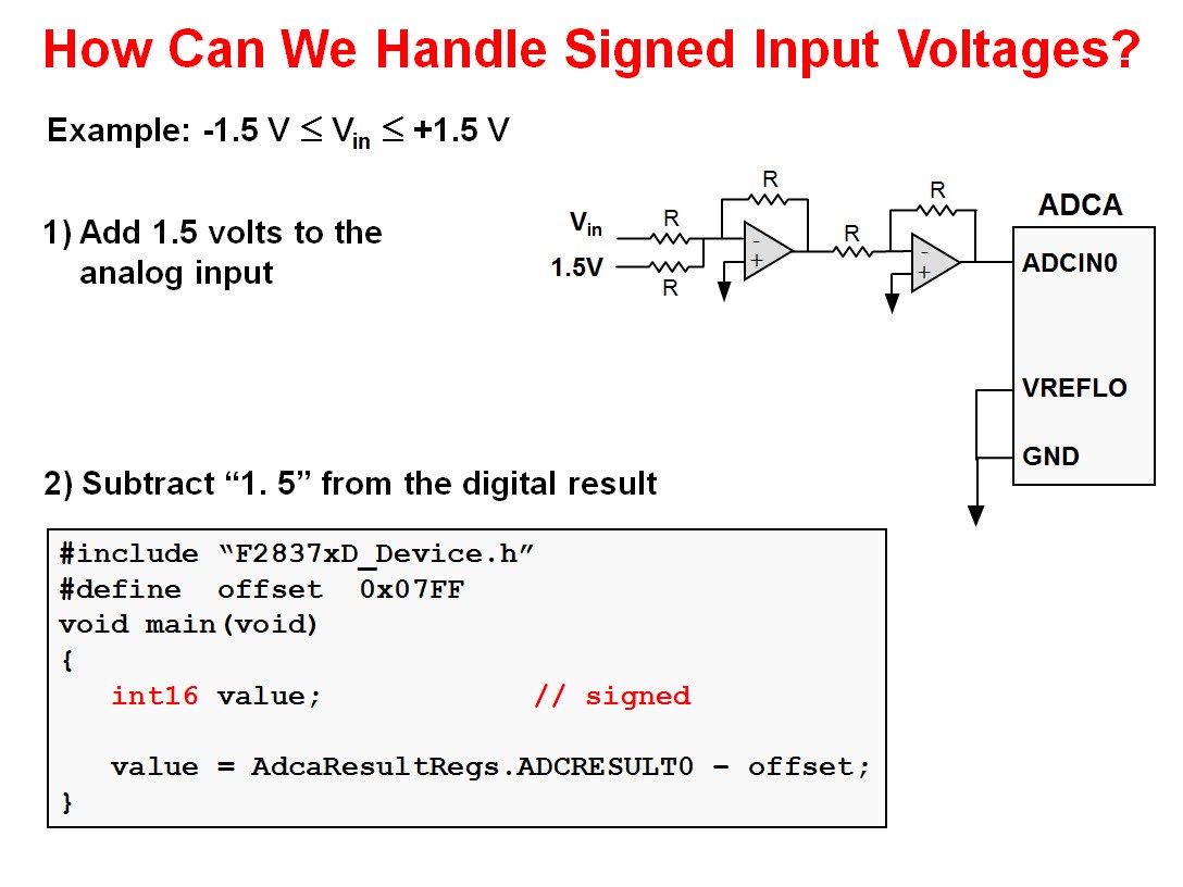
    You are correct, the input signal to the ADC needs to be between 0 - 3 V.  For signed magnitude signal between -1 V and +1 V you will need to add 1 V to the analog input and then subtract 1 V from the digital result.  Please see the following slide from the F28x7x workshop (similar for the F2833x):

    For the F28335, the code would be:

    #include “DSP2833x_Device.h”

    #define offset 0x07FF

    void main(void)

    {

       int16 value;                                       // signed


       value = AdcMirror.ADCRESULT0 – offset;

    }

    I hope this helps. If this answers your question, please click the green "Verified Answer" button. Thanks.

    - Ken

  • Thanks for replying Ken Schachter

    I am not doing DSP coding. I am interfacing DSP kit to matlab 2016a. How will it happen in matlab ?
  • Gaurav,

    I think you need external signal conditioning (DC voltage adder) to convert -1/ +1 V to 0-3V, so the C2000 device can read in the signal. Then inside of Simulink, you can software scale it back to -1 / +1 as needed (several ways to do this, subtract a DC offset, or use a 1D-lookup table, etc).

    Cheers,

    -Brian

  • Gaurav,

    Yes, as Brian has pointed out this is an ADC hardware issue before using Simulink. The constraints of the ADC input is 0-3V, and using negative voltage on the ADC input pin can damage the channel (see data sheet).

    I hope this helps. If this answers your question, please click the green "Verified Answer" button. Thanks.

    - Ken
  • Hi gurve how did you solve your problem???I am facing same problem....Please help me on kami_zeb@yahoo.com. Bundle of thanks
  • Gaurav,

    It's been a while since we have heard from you last. Therefore, we are assuming you were able to resolve your issue. If this isn’t the case, please reject this resolution or reply to this thread. If this thread locks, please make a new thread describing the current status of your issue. Thank you.

    - Ken