This thread has been locked.

If you have a related question, please click the "Ask a related question" button in the top right corner. The newly created question will be automatically linked to this question.

CCS/TMS320F28377D: wrong ADC values of a single ADC module

Part Number: TMS320F28377D
Other Parts Discussed in Thread: CONTROLSUITE

Tool/software: Code Composer Studio

Hello,

I am trying to convert a 2.5V DC voltage without essential noise via the channels ADCDIN2 and ADCDIN3 (voltage is applicated on both channels and was measured via a multimeter directly at the ADC channel pins) of the ADCD module on my microcontroller. The control of the AdcdRegsiters is given to CPU2 and the triggering of the two SOCs is done by CPU2 too. Both projects (one project per core) are projects with Operating System. The two SOCs are triggered by the clock module of the OS every 10 milliseconds. The expected value is 2.5/3.3*4096=3103, since I am operating in 12-bit resolution.

The problem presents itself as follows: AdcdResultRegister shows values round about 2300 instead of the expected round about 3100.

What I have observed: I have also ADCA module working as expected without errors in my application  which I initialize and trigger (I will post my code later at the end of my text) the exact same way as ADCD module.

What I have observed by accident: When I load the .out file of CPU1 on CPU2, let it run, don't reset the device, after that load the correct .out file of CPU2 on CPU2 and let this program run, the ADCD module works as expected and shows values round about 3000-3100 in the AdcdResultRegister! When I reset the device I must run CPU1 .out file on CPU2 first before the ADCD works as expected again. Seems to me, that something in the .out file of CPU1 initializes something in the microcontroller, that is required for ADCD module to work properly (but apparently not necessary for ADCA module, since this works fine with normal load and running of the cores), that is deleted when the device is reset.

I hope you have some advice for me and I say thanks in advance.


Code of CPU1:

main_1.c:

Int main()
{ 
    System_printf("enter main()\n");
	InitGpio();
	InitDrehzahlsensoren();
	InitSF_DC_Test();
#ifdef _STANDALONE
	IPCBootCPU2(C1C2_BROM_BOOTMODE_BOOT_FROM_FLASH);
#endif
    BIOS_start();
    return(0);
}


Drehzahlsensoren_1.c:

#include <Drehzahlsensoren_1.h>


//Initialisiert die ECap1 Peripherie, die die Flanken des Drehzahlsensors 1 erkennt
void InitDrehzahlerkennung_1()
{
	EALLOW;
	InputXbarRegs.INPUTSELECTLOCK.bit.INPUT7SELECT = 0;		//INPUTXBAR7 Einstellungen werden freigeschaltet
	InputXbarRegs.INPUT7SELECT = 94;						//GPIO 94 wird mit INPUTXBAR7 verbunden
	InputXbarRegs.INPUTSELECTLOCK.bit.INPUT7SELECT = 1;		//INPUTXBAR7 Einstellungen werden verriegelt
	DevCfgRegs.CPUSEL1.bit.ECAP1 = 1;						//ECap1 Register werden mit CPU2 verbunden
	EDIS;
}

//Initialisiert die ECap2 Peripherie, die die Flanken des Drehzahlsensors 2 erkennt
void InitDrehzahlerkennung_2()
{
	EALLOW;
	InputXbarRegs.INPUTSELECTLOCK.bit.INPUT8SELECT = 0;		//INPUTXBAR8 Einstellungen werden freigeschaltet
	InputXbarRegs.INPUT8SELECT = 90;						//GPIO 94 wird mit INPUTXBAR8 verbunden
	InputXbarRegs.INPUTSELECTLOCK.bit.INPUT8SELECT = 1;		//INPUTXBAR8 Einstellungen werden verriegelt
	DevCfgRegs.CPUSEL1.bit.ECAP2 = 1;						//ECap2 Register werden mit CPU2 verbunden
	EDIS;
}

void InitDS_DC_Test()
{
	EALLOW;
	DevCfgRegs.CPUSEL11.bit.ADC_D = 1;		//ADCD Register werden mit CPU2 verbunden
	EDIS;
}

//Initialisiert die ECap3 Peripherie, die das PWM Signal für den ersten ADC erzeugt
void InitADC1MCLK()
{
	GPIO_SetupPinMux(3, GPIO_MUX_CPU1, 2);					//GPIO3 wird von CPU1 gesteuert und mit OUTPUTXBAR2 verbunden
	GPIO_SetupPinOptions(3, GPIO_OUTPUT, GPIO_PUSHPULL);	//GPIO3 wird als Output konfiguriert
	EALLOW;
	OutputXbarRegs.OUTPUT2MUX0TO15CFG.bit.MUX4 = 3;			//Der ECap3 Output wird mit MUX4 der OUTPUTXBAR2 verbunden
	OutputXbarRegs.OUTPUT2MUXENABLE.bit.MUX4 = 1;			//Der Slot MUX4 der OUTPUTXBAR2 wird aktiviert
	DevCfgRegs.CPUSEL1.bit.ECAP3 = 1;						//ECap3 Register werden mit CPU2 verbunden
	EDIS;
}

//Initialisiert die ECap4 Peripherie, die das PWM Signal für den zweiten ADC erzeugt
void InitADC2MCLK()
{
	GPIO_SetupPinMux(2, GPIO_MUX_CPU2, 5);					//GPIO2 wird von CPU2 gesteuert und mit OUTPUTXBAR1 verbunden
	GPIO_SetupPinOptions(2, GPIO_OUTPUT, GPIO_PUSHPULL);	//GPIO2 wird als Output konfiguriert
	EALLOW;
	OutputXbarRegs.OUTPUT1MUX0TO15CFG.bit.MUX6 = 3;			//Der ECap3 Output wird mit MUX4 der OUTPUTXBAR1 verbunden
	OutputXbarRegs.OUTPUT1MUXENABLE.bit.MUX6 = 1;			//Der Slot MUX4 der OUTPUTXBAR1 wird aktiviert
	DevCfgRegs.CPUSEL1.bit.ECAP4 = 1;						//ECap4 Register werden mit CPU2 verbunden
	EDIS;
}

void InitDrehzahlsensoren()
{
	InitDrehzahlerkennung_1();
	InitDrehzahlerkennung_2();
	InitADC1MCLK();
	InitADC2MCLK();
	InitDS_DC_Test();
}


Schwingungsfuehler_1.c:

#include "Schwingungsfuehler_1.h"

void InitSF_DC_Test()
{
	EALLOW;
	DevCfgRegs.CPUSEL11.bit.ADC_A = 1;		//ADCA Register werden mit CPU2 verbunden
	EDIS;
}

Code of CPU2:


main_2.c:

#include <xdc/std.h>
#include <xdc/runtime/System.h>
#include <ti/sysbios/BIOS.h>
#include <ti/sysbios/knl/Task.h>
#include "main_2.h"

Int main()
{ 
    System_printf("enter main()\n");
    InitDrehzahlsensoren();
    InitSF_DC_Test();
    BIOS_start();
    return(0);
}

Drehzahlsensoren_2.c:

#include <Drehzahlsensoren_2.h>

//Initialisiert die ECap1 Peripherie, die die Flanken des Drehzahlsensors 1 erkennt
void InitDrehzahlerkennung_1()
{
    EALLOW;
    CpuSysRegs.PCLKCR3.bit.ECAP1 = 1;                        //ECap1 bekommt den Betriebstakt
    ECap1Regs.ECCTL1.bit.CAP1POL = 0;                        //CEVT1 wird bei steigender Flanke gefeuert
    ECap1Regs.ECCTL1.bit.CAP2POL = 0;                        //CEVT2 wird bei steigender Flanke gefeuert
    ECap1Regs.ECCTL1.bit.CAP3POL = 0;                        //CEVT3 wird bei steigender Flanke gefeuert
    ECap1Regs.ECCTL1.bit.CAP4POL = 0;                        //CEVT4 wird bei steigender Flanke gefeuert
    ECap1Regs.ECCTL1.bit.CTRRST1 = 1;                        //Zähler wird nach CEVT1 zurückgesetzt
    ECap1Regs.ECCTL1.bit.CTRRST2 = 1;                        //Zähler wird nach CEVT2 zurückgesetzt
    ECap1Regs.ECCTL1.bit.CTRRST3 = 1;                        //Zähler wird nach CEVT3 zurückgesetzt
    ECap1Regs.ECCTL1.bit.CTRRST4 = 1;                        //Zähler wird nach CEVT4 zurückgesetzt
    ECap1Regs.ECCTL1.bit.CAPLDEN = 1;                        //CAP Register werden mit Time-Stamps der jeweiligen CEVTs geladen
    ECap1Regs.ECCTL2.bit.TSCTRSTOP = 1;                        //Zähler des ECAP1 wird gestartet
    ECap1Regs.ECEINT.bit.CEVT1 = 1;                            //CEVT1 feuert einen ECap1-Interrupt in Richtung CPU
    EDIS;
}

//Initialisiert die ECap2 Peripherie, die die Flanken des Drehzahlsensors 2 erkennt
void InitDrehzahlerkennung_2()
{
    EALLOW;
    CpuSysRegs.PCLKCR3.bit.ECAP2 = 1;        //ECap2 bekommt den Betriebstakt
    ECap2Regs.ECCTL1.bit.CAP1POL = 0;        //CEVT1 wird bei steigender Flanke gefeuert
    ECap2Regs.ECCTL1.bit.CAP2POL = 0;        //CEVT2 wird bei steigender Flanke gefeuert
    ECap2Regs.ECCTL1.bit.CAP3POL = 0;        //CEVT3 wird bei steigender Flanke gefeuert
    ECap2Regs.ECCTL1.bit.CAP4POL = 0;        //CEVT4 wird bei steigender Flanke gefeuert
    ECap2Regs.ECCTL1.bit.CTRRST1 = 1;        //Zähler wird nach CEVT1 zurückgesetzt
    ECap2Regs.ECCTL1.bit.CTRRST2 = 1;        //Zähler wird nach CEVT2 zurückgesetzt
    ECap2Regs.ECCTL1.bit.CTRRST3 = 1;        //Zähler wird nach CEVT3 zurückgesetzt
    ECap2Regs.ECCTL1.bit.CTRRST4 = 1;        //Zähler wird nach CEVT4 zurückgesetzt
    ECap2Regs.ECCTL1.bit.CAPLDEN = 1;        //CAP Register werden mit Time-Stamps der jeweiligen CEVTs geladen
    ECap2Regs.ECCTL2.bit.TSCTRSTOP = 1;        //Zähler des ECAP2 wird gestartet
    ECap2Regs.ECEINT.bit.CEVT1 = 1;            //CEVT1 feuert einen ECap2-Interrupt in Richtung CPU
    EDIS;
}

void InitDS_DC_Test()
{
    EALLOW;
    CpuSysRegs.PCLKCR13.bit.ADC_D = 1;                //ADCD bekommt den Betriebstakt
    AdcdRegs.ADCCTL2.bit.PRESCALE = 6;                //ADCLK = SYSCLK/4
    AdcSetMode(ADC_ADCD, ADC_RESOLUTION_12BIT        //ADCD auf 12 bit Auflösung und Singlemode eingestellt
                   , ADC_SIGNALMODE_SINGLE);
    AdcdRegs.ADCCTL1.bit.ADCPWDNZ = 1;                //ADCD wird eingeschaltet
    DELAY_US(1000);                                    //1 ms Wartezeit um ADCD komplett hochfahren zu lassen
    AdcdRegs.ADCSOC0CTL.bit.CHSEL = 2;                //SOC0 konvertiert Kanal 2
    AdcdRegs.ADCSOC0CTL.bit.ACQPS = 15;                //SOC0 S&H Window wird auf 16 SYSCLKs eingestellt
    AdcdRegs.ADCSOC0CTL.bit.TRIGSEL = 0;            //SOC0 wird mittels Software getriggert
    AdcdRegs.ADCSOC1CTL.bit.CHSEL = 3;                //SOC1 konvertiert Kanal 3
    AdcdRegs.ADCSOC1CTL.bit.ACQPS = 15;                //SOC1 S&H Window wird auf 16 SYSCLKs eingestellt
    AdcdRegs.ADCSOC1CTL.bit.TRIGSEL = 0;            //SOC1 wird mittels Software getriggert
    EDIS;
}

void starteADCWandlungDS_DC()        //alle 10ms
{
    AdcdRegs.ADCSOCFRC1.bit.SOC0 = 1;    //SOC0 wird getriggert; Abtastung Kanal 2
    AdcdRegs.ADCSOCFRC1.bit.SOC1 = 1;    //SOC1 wird getriggert; Abtastung Kanal 3
}

//Initialisiert die ECap3 Peripherie, die das PWM Signal für den ersten ADC erzeugt
void InitADC1MCLK()
{
    CpuSysRegs.PCLKCR3.bit.ECAP3 = 1;                        //ECap3 bekommt den Betriebstakt
    ECap3Regs.ECCTL2.bit.CAP_APWM = 1;                        //ECap3 arbeitet im AWPM Modus
    ECap3Regs.CAP1 = 20000000;                                //Die Periodendauer der PWM beträgt 100ms
    ECap3Regs.CAP2 = 5000000;                                //Die On Time der PWM beträgt 25 ms
    ECap3Regs.ECCTL2.bit.TSCTRSTOP = 1;                        //Der Zähler des ECap3 wird gestartet
    EDIS;
}

//Initialisiert die ECap4 Peripherie, die das PWM Signal für den zweiten ADC erzeugt
void InitADC2MCLK()
{
    EALLOW;
    CpuSysRegs.PCLKCR3.bit.ECAP4 = 1;                        //ECap4 bekommt den Betriebstakt
    ECap4Regs.ECCTL2.bit.CAP_APWM = 1;                        //ECap4 arbeitet im AWPM Modus
    ECap4Regs.CAP1 = 20000000;                                //Die Periodendauer der PWM beträgt 100ms
    ECap4Regs.CAP2 = 5000000;                                //Die On Time der PWM beträgt 25 ms
    ECap4Regs.ECCTL2.bit.TSCTRSTOP = 1;                        //Der Zähler des ECap4 wird gestartet
    EDIS;
}

//Interrupt-Routine zum Verarbeiten der Time Stamps des ECap1-Moduls für die Berechnung
//von Drehzahl und Periodendauer
void hole_TimeStamps_1()
{
    rpm_1 = (1.0/(ECap1Regs.CAP1*(1.0/CPU_FREQ)))*60.0;    //Berechnung der Drehzahl
    periode_1 = ECap1Regs.CAP1*(1.0/CPU_FREQ);            //Berechnung der Periodendauer
    ECap1Regs.ECCLR.bit.CEVT1 = 1;                        //CEVT1 Interrupt-Flag löschen
    ECap1Regs.ECCLR.bit.INT = 1;                        //ECap1-Interrupt-Flag löschen
}

//Interrupt-Routine zum Verarbeiten der Time Stamps des ECap2-Moduls für die Berechnung
//von Drehzahl und Periodendauer
void hole_TimeStamps_2()
{
    rpm_2 = (1.0/(ECap2Regs.CAP1*(1.0/CPU_FREQ)))*60.0;    //Berechnung der Drehzahl
    periode_2 = ECap2Regs.CAP1*(1.0/CPU_FREQ);            //Berechnung der Periodendauer
    ECap2Regs.ECCLR.bit.CEVT1 = 1;                        //CEVT1 Interrupt-Flag löschen
    ECap2Regs.ECCLR.bit.INT = 1;                        //ECap2-Interrupt-Flag löschen
}

void DS_DC_Test_1()
{
    power_ds1 = AdcdResultRegs.ADCRESULT0;
}

void DS_DC_Test_2()
{
    power_ds2 = AdcdResultRegs.ADCRESULT1;
}

void InitDrehzahlsensoren()
{
    InitDrehzahlerkennung_1();
    InitDrehzahlerkennung_2();
    InitADC1MCLK();
    InitADC2MCLK();
    InitDS_DC_Test();
}

Schwingungsfuehler_2.c:

#include "Schwingungsfuehler_2.h"

void InitSF_DC_Test()
{
	EALLOW;
	CpuSysRegs.PCLKCR13.bit.ADC_A = 1;				//ADCA bekommt den Betriebstakt
	AdcaRegs.ADCCTL2.bit.PRESCALE = 6;				//ADCLK = SYSCLK/4
	AdcSetMode(ADC_ADCA, ADC_RESOLUTION_12BIT		//ADCA auf 12 bit Auflösung und Singlemode eingestellt
	           , ADC_SIGNALMODE_SINGLE);
	AdcaRegs.ADCCTL1.bit.ADCPWDNZ = 1;				//ADCA wird eingeschaltet
	DELAY_US(1000);									//1 ms Wartezeit um ADCA komplett hochfahren zu lassen
	AdcaRegs.ADCSOC0CTL.bit.CHSEL = 0;				//SOC0 konvertiert Kanal 0
	AdcaRegs.ADCSOC0CTL.bit.ACQPS = 15;				//SOC0 S&H Window wird auf 16 SYSCLKs eingestellt
	AdcaRegs.ADCSOC0CTL.bit.TRIGSEL = 0;			//SOC0 wird mittels Software getriggert
	AdcaRegs.ADCSOC1CTL.bit.CHSEL = 1;				//SOC1 konvertiert Kanal 1
	AdcaRegs.ADCSOC1CTL.bit.ACQPS = 15;				//SOC1 S&H Window wird auf 16 SYSCLKs eingestellt
	AdcaRegs.ADCSOC1CTL.bit.TRIGSEL = 0;			//SOC1 wird mittels Software getriggert
	EDIS;
}

void starteADCWandlungSF_DC()		//alle 10ms
{
	AdcaRegs.ADCSOCFRC1.bit.SOC0 = 1;	//SOC0 wird getriggert; Abtastung Kanal 0
	AdcaRegs.ADCSOCFRC1.bit.SOC1 = 1;	//SOC1 wird getriggert; Abtastung Kanal 1
}

void SF_DC_Test_1()		//alle 10ms
{
	if(periode_1 > 0.1)									//wenn Unwuchtsignal unter 10Hz (600 U/min)
	{
		static Uint16 counter = 0;						//Zählervariable für bereits abgetastete Werte
		static Uint32 mittelwert_summe = 0;				//Variable für das Aufsummieren der Abtastwerte
		mittelwert_summe += AdcaResultRegs.ADCRESULT0;	//Aufsummieren des aktuellen Abtastwertes
		counter++;										//Erhöhen der Zählervariable
		if(counter >= periode_1/0.01)					//wenn eine Periode abgetastet wurde
		{
			mittelwert_summe /= counter;				//Division der Summe der Abtastwerte durch Anzahl der Abtastwerte
			dc_sf_signal_1 = mittelwert_summe;				//Gleichspannung des ersten SFs beträgt ermittelten Mittelwert
			mittelwert_summe = 0;						//Summenvariable zurücksetzen für neue Berechnung
			counter = 0;								//Zählervariable zurücksetzen für neue Berechnung
		}
	}else												//wenn Unwuchtsignal über 10Hz (600 U/min)
	{
		dc_sf_signal_1 = AdcaResultRegs.ADCRESULT0;			//Gleichspannung des ersten SFs ist der aktuelle Abtastwert
	}
}

void SF_DC_Test_2()		//alle 10ms
{
	if(periode_2 > 0.1)									//wenn Unwuchtsignal unter 10Hz (600 U/min)
	{
		static Uint16 counter = 0;						//Zählervariable für bereits abgetastete Werte
		static Uint32 mittelwert_summe = 0;				//Variable für das Aufsummieren der Abtastwerte
		mittelwert_summe += AdcaResultRegs.ADCRESULT1;	//Aufsummieren des aktuellen Abtastwertes
		counter++;										//Erhöhen der Zählervariable
		if(counter >= periode_2/0.01)					//wenn eine Periode abgetastet wurde
		{
			mittelwert_summe /= counter;				//Division der Summe der Abtastwerte durch Anzahl der Abtastwerte
			dc_sf_signal_2 = mittelwert_summe;				//Gleichspannung des zweiten SFs beträgt ermittelten Mittelwert
			mittelwert_summe = 0;						//Summenvariable zurücksetzen für neue Berechnung
			counter = 0;								//Zählervariable zurücksetzen für neue Berechnung
		}
	}else												//wenn Unwuchtsignal über 10Hz (600 U/min)
	{
		dc_sf_signal_2 = AdcaResultRegs.ADCRESULT1;			//Gleichspannung des zweiten SFs ist der aktuelle Abtastwert
	}
}


  • Hi Alexander,

    Is this a TI board or a custom board for your application? I wouldn't expect to see VREFHI = 3.3V, but instead for it to be 2.5V or 3.0V.

    I think the first step to debug would be to load and run the CPU2 code on CPU2 and then check the settings for ADC-D vs. ADC-A in the expressions window. Check the basic stuff like is the ADC powered up, is the clock enabled, are the SOC channel, S+H, and trigger select correct, etc.

    Now run the code for CPU1 on CPU2 and again examine the ADC-D registers to see what has changed.

    If you don't find that any of the ADC-D registers have changed, then you probably have some issue with the ADC trigger that CPU1 code is solving; you can apply a similar debug strategy and examine the registers in both situations.
  • Hi Devin,

    thanks for your reply,

    I am working with a custom board and I ensured the 3.3V at VERFHI by measurement with multimeter.

    I also checked the ADCA and ADCD settings in their registers, there are no differences, when I run CPU2 code on CPU2.

    Even when I then run CPU1 code on CPU2 there are no differences between ADCA an ADCD registers.

    Also there are no differences between ADCD reigsters themselves in both cases. (The ADCD registers have the same condition in case ADCD module works right vs. the case it works not right).

    The ADCSOCxCTL registers behave the same as the ADCD registers, no change between module ADCA and ADCD (after CPU1 code run and after CPU2 code run) and no change between right working case and non right working case.

    Any other ideas?

  • another observation I made: When I reset my (custom) development board by turning the power off, the ADCD module works right even when I dont let run CPU1 code on CPU2 at first. Seems like the reset via CCS debugger acts different as the reset via unplug the power from the development board.
  • Hi Alexander,

    Definitely a strange issue.  

    Some other things to check:

    • Are you sure the clock settings are correct for both cores?  You can get a debug clock out on a pin and then measure it by:
      • Selecting various clocks by changing the XCLKOUTSEL field of the CLKSRCCTL3 register.  Of interest are probably CPU1.SYSCLK and CPU2.SYSCLK
      • Enable XCLKOUT in gpio mux for GPIO73
      • Set (or at least just understand the default) XCLKOUT divider in XCLKOUTDIVSEL register
    • If you input a signal to ADCIN14 or ADCIN15, the same pin voltage is fanned out to internal ADC connections on all ADCs.  This might be a good way to check that you are forcing the exact same signal to both ADCs if your HW can use these pins. 

  • Hi,

    I have tested all the things Devin suggested me: the SYSCLK is 200MHz for both cores, everything correct.
    When I apply a voltage to ADCIN14 and 15 ADCD reads the voltage correct.
    Seems like it has something to do with the voltages I apply to my inputs at ADCD module.

    I have made following observation:
    When I increase the Sample and Hold Window Size of the concerned inputs in the software the ADCD module displays correct values.

    I tried to explain this to me:
    I apply the voltage via a voltage divider to the inputs. I can imagine that the path with the capacitive S&H circuit becomes so low-resistant in the moment of closing the circuit that the ratio of the voltage divider changes so much that the voltage at my input collapses or at least becomes lower than the expected value. How fast discharges the hold capacitor its load when S&H circuit is open? (I wonder why voltage doesnt get higher by steps until it reaches its final value of 2.5V everytime the S&H circuit closes even when the S&H window size is too small).

    And now the thing i CANNOT explain to me:
    When I reset the device it doenst work properly (without increasing the S&H window in software).
    When I just load the program and run the cores it works properly (without increasing the S&H window in software)
    Obviously something in reset procedure increases my S&H window size without letting me know (registers dont show any changes in ACQPS) very strange thing!!


    Something happens in the different RESET PROCEDURES (debugger reset, por reset, etc...) that I DONT UNDERSTAND.

    Perhaps somebody can show me what happens in the different reset procedures (which registers are deleted, which configurations are reset, etc....)

    Thanks in advance
  • Hi Alexander,

    There is a model of the ADC input in the datasheet in the section "Single-Ended Input Model".  You should assume that the S+H capacitor, Ch, could be any value at the start of the S+H phase.  

    If you are using a voltage divider you will likely need an op-amp, to increase the S+H duration significantly, or to place a large capacitor on the ADC input.  Increasing the S+H duration (by increasing ACQPS) will make the sampling take longer, increasing sample-to-output latency.  Adding a large capacitor on the pin will result in a sample-rate limitation, otherwise charge will bleed off the external capacitor faster than it can be re-charged (and there will be a significant reduction in input bandwidth, which could be good or bad).  An op-amp will require board area/cost.  

    What is strange is that you do sometimes get good results without increasing the S+H duration.  Really the only thing that should affect S+H duration is ACQPS setting and SYSCLK speed, both of which you have confirmed to be the same between both reset scenarios?  

  • I FOUND THE ERROR! But unfortunately not the cause!

    I implemented another application during the last days which uses the ECap modules.
    Here I can also observe different behaviours between different reset (program load) scenarios.
    I found out that the SYSCLK isnt the same in both cases (somehow havent measured properly after Devins advice, sorry for that), because in one case there were counted wrong values in the ECap.CAP1 registers by an exact factor of 20! (Seems like integral multiplier of PLL) In the other case right values were counted. AFAIK the only reason for that is a different clock speed in both cases. This would explain the different S&H window durations in the different reset scenarios (is a program flash a reset at all???, what happens exactly at a program flash?? Feels to me like there is happening a whole bunch of things that I cant comprehend and that I cant see in my debugger when I flash the program or reset the device or cores) although same ACQPS value from my original thread opening application.
    Right after flashing the programs on both cores when I start both cores successively with their right programs (CPU1 code on CPU1 CPU2 code on CPU2) I found out that CPU1.SYSCLK is 10 MHz(!!!) (via XCLKOUT on gpio73) which isnt right because I have adjusted it to be 200MHz by the multipliers in the BIOS.
    My ECap modules indeed run on CPU2 but since CPU2.SYSCLK is directly derived from CPU1.SYSCLK there is no difference between them.
    Now when I reset CPU1 by debugger in CCS the SYSCLK is perfectly at the adjusted value of 200 MHz.
    Seems like the SYSCLK gets not adjusted properly when I click on debug in CCS and the programs get flashed but after a core reset by the debugger it GETS adjusted properly.

    Can anybody explain this behaviour to me?
  • Hi Alexander,

    I'll notify the PLL/Clocking expert to follow up with you. In the meantime, it may speed debug up if you can describe how and when you configure the clocks in your system and post snippets of the initialization code.
  • Hi Devin,

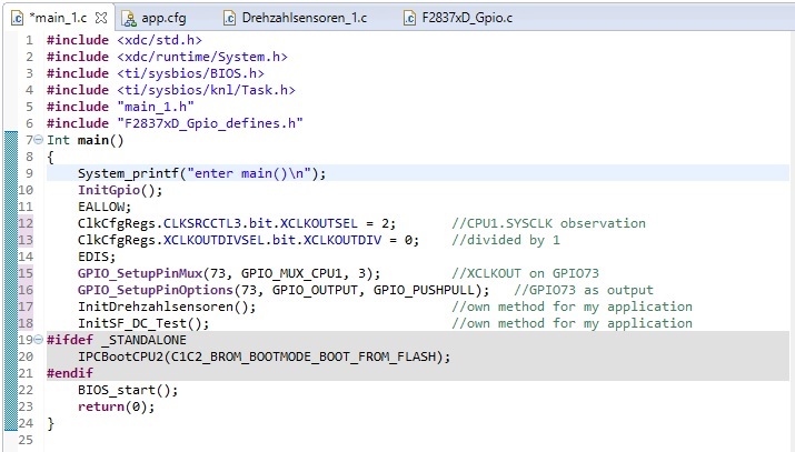
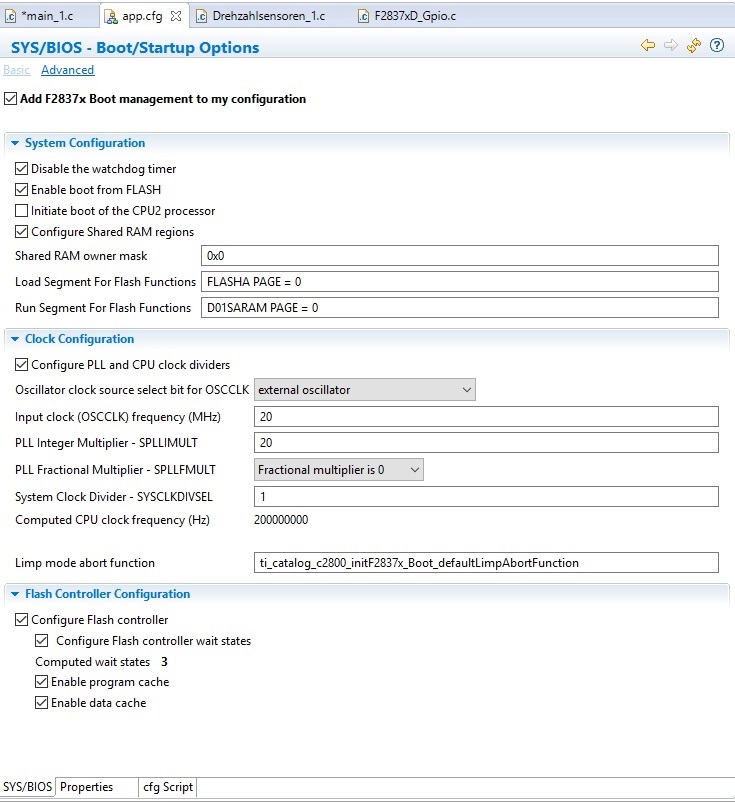
    I attached screenshots of my main method and my BIOS configuration (where PLL/clocking adjustments are made).

    Dont hesitate to come up to me for further details if you need them.

    I say thanks in advance

  • Hi Alexander,

    In response to the SYSCLK frequency not being as expected:

    Looking at the snippet of your code it looks like you are bringing out SYSCLK on GPIO73 without dividing it down (XCLKOUTDIV=0x0). This will not work, because the IO buffer cannot toggle that fast, so even if the SYSCLK is running at higher speed, if you do not divide the clock down, the IO will not support such fast toggling (in this case it is 200MHz). Maximum clock frequency recommended to bring out on GPIO is 50MHz.

    Can you change the code to use the XCLKOUTDIV=0x3 (divide by 8)? This will divide the SYSCLK by 8 i.e. 200MHz/8 = 25MHz. So, if the PLL is locked correctly you should observe 25MHz on GPIO73.

    Regards,
    Nirav
  • Hi Nirav,

    When I leave the XCLKOUTDIV at its value of 0x0 I can see the 10MHz on my oscilloscope directly after flashing the program and starting the core. (faulty case; SYSCLK incorrect by a factor of exactly 20)

    Same XCLKOUTDIV of 0x0 shows me 200 MHz on my oscilloscope after debugger reset of the core. (correct case)

    When I set the XCLKOUTDIV to a value of 0x3 (division by 8) I can see the 1.25MHz on my oscilloscop directly after flashing the program and starting the core. (faulty case; SYSCLK incorrect by a factor of exactly 20)

    Same XCLKOUTDIV of 0x3 shows me 25 MHz on my oscilloscope after debugger reset of the core. (correct case)

    Now the question is WHY is my SYSCLK faulty in the one case (just flashing the program and starting the core) and correct in the other case (after debugger reset of the core and then starting the core)

    I have observed that the IMULT in the SYSPLLMULT register has a decimal value of 20 in the correct case and a value of 0 in the faulty case. (WHY???)  This corresponds perfectly to my described failure beahviour.

    Would be thankful for more advices WHY my IMULT is different in the different cases.

    I say thanks in advance

  • Hi Alexander,

    Based on your observation that you described, it looks like PLL is not configured when you are measuring faulty SYSCLK i.e. 10MHz/1.25MHz(div/3), 10MHz is coming from INTOSC2 which is the default SYSCLK.

    Can you please clarify:
    1. When does the PLL configuration happen? Based on your snippet you bring out XCLKOUT right at the start of your code, hence initially you will see 10MHz on GPIO73 (since the default SYSCLK=INTOSC2=10MHz), until you configure PLL to SYSCLK=200MHz.

    2. What does BIOS_start() function do? Does it program the code into FLASH which includes code for PLL configuration?


    Regards,
    Nirav
  • Hi Nirav,

    indeed in case of faulty SYSCLK there is not only an IMULT of 0 in the SYSPLLMULT register but a OSCCLKSRCSEL value of 0 in CLKSRCCTL1 regsiter too. Seems like the complete clock configuration is not happening in the fault case.

    Nirav Ginwala said:
    Can you please clarify:

    1. When does the PLL configuration happen? Based on your snippet you bring out XCLKOUT right at the start of your code, hence initially you will see 10MHz on GPIO73 (since the default SYSCLK=INTOSC2=10MHz), until you configure PLL to SYSCLK=200MHz.

    I dont know WHEN exactly the PLL configuration is happening I just created a CCS project with operating system and used the given CCS template. Then I configured the app.cfg as you can see in my screenshot above. Perhaps an operating system expert can say WHEN the clock configuration actually happens.

    Nirav Ginwala said:
    2. What does BIOS_start() function do? Does it program the code into FLASH which includes code for PLL configuration?

    BIOS_start() function is inserted in main method code by default when a CCS project with operating system is created. I think it starts the scheduling of the operating system with all of its tasks, clocks, timers, etc.. Perhaps an expert for operating system is more competent here too.

    Regards, Alexander

  • Hi Alexander,

    What version of SYS/BIOS are you using?

    Todd
  • Hi,

    I am using version 6.52.00.12.

    Alexander

  • Hi,

    another observation I made:
    when I only flash the program on CPU1 I can see the ClkCfgRegs in their proper state with the values that are expected (OSCCLKSRC = external oscillator, IMULT = 20).
    Now when I flash the program on CPU2 and look at the CPU1 again to watch its registers I see its ClkCfgRegs holding the default values (OSCCLKSRC = internal oscillator 2, IMULT = 0), which are faulty.
    Now when I restart the CPU1 and let it run to its main() the values are in their proper state again.

    So it seems to me like something in the flash/boot process (until it stops right before main()) of CPU2 clears the ClkCfgRegs of CPU1 and/or sets them to their default values, so that I have to run CPU1's reset/boot procedure again to have the proper Clock/PLL Settings.

    Anybody has an idea about that?

    Greets Alexander

  • Alexander,

    Have you tried to use ControlSuite APIs to set up the clocking once you get into main?

    Todd
  • Can I mark this a resolved?

    Todd
  • Hi,

    sorry no, it is NOT solved.

    I have also tried set up the clock "by hand" with API functions in my main method. In this case everything worked fine as expected.

    Greetings Alex

  • Alexander,

    Can you attach the "by hand" code you did to get it to work?

    Todd
  • Int main()
    { 
        System_printf("enter main()\n");
    	InitGpio();
    	InitSysPll(1, 20, 0, 0);		//by hand code
    	InitDrehzahlsensoren();
    	InitSF_DC_Test();
    	InitADCs_ext();
    	InitHMS();
    #ifdef _STANDALONE
    	IPCBootCPU2(C1C2_BROM_BOOTMODE_BOOT_FROM_FLASH);
    #endif
        BIOS_start();
        return(0);
    }

  • Hi Alexander,

    I opened a Jira ticket on this: SYSBIOS-694

    We'll get back to you when we have more information. It sounds like you have a work-around for now, so I'm going to mark this as "TI Thinks Resolved" and we will track it internally with the Jira ticket.

    Note: I expect this will take awhile to resolve since it is not a high priority (due to an available work-around). This thread may get locked in the meantime. We'll unlock it and post updates.

    Todd