


Other Parts Discussed in Thread: SYSBIOS
Tool/software: TI-RTOS
Hi,
I have trouble putting .bss section in external SRAM connected through EPI.
Configuration:
Target F28M35H52C1 (Cortex-M3 + C2000 DSP) CCS Version: 5.5.0.00077 Compiler TI v5.1.1 IPC 3.10.1.11 SYS/BIOS 6.35.04.50 TI RTOS 1.20.0.28
Hardware is a custom board with F28M35H52C1 processor, 2 Mbyte external SRAM (Alliance Memory AS6C1616-55TIN) and LCD controller (EPSON S1D13742) on EPI bus.
I already use this external SRAM to store GUI images (1Mbyte) and the display buffer (768 Kbytes), some other sections, which all works fine, and ARM_EXTRAM section where I want to store .bss.
Here is an extract of the cmd file:
MEMORY
{
EXTRAM (RW) : origin = 0x60020D00, length = 0xBB800
EXTRAM_BIN (RW) : origin = 0x600DC500, length = 0x100000
ARM_EXTRAM (RWX) : origin = 0x601E6E10, length = 0x191F0
}
SECTIONS
{
.SDRRAM : > EXTRAM
.REMOTE_BIN : > EXTRAM_BIN
.bss : > ARM_EXTRAM
}
EXTRAM and EXTRAM_BIN are used with #pragma:
#pragma DATA_SECTION(GuiLib_DisplayBuf,".SDRRAM")
#pragma DATA_SECTION(SD_Card_RamBuffer,".REMOTE_BIN")
EPI is configured with EPI_Init() in EPI_config.c (see attachment below) which is called in those two functions:
//###########################################################################
// FILE:   EPI_config.c
// TITLE:  EPI Interface
//###########################################################################

// Definitions
#define EXTERNAL_DISPLAY_ADDR 		    0xA0000000
#define EXTERNAL_RAM_ADDR 				0x60000000

static void SetPortControl(void);

void EPI_Init()
{
	// Enable Clock for EPI & GPIO Ports
	SysCtlPeripheralEnable(SYSCTL_PERIPH_EPI0);
	SysCtlPeripheralEnable(SYSCTL_PERIPH_GPIOC);
	SysCtlPeripheralEnable(SYSCTL_PERIPH_GPIOD);
	SysCtlPeripheralEnable(SYSCTL_PERIPH_GPIOE);
	SysCtlPeripheralEnable(SYSCTL_PERIPH_GPIOF);
	SysCtlPeripheralEnable(SYSCTL_PERIPH_GPIOG);
	SysCtlPeripheralEnable(SYSCTL_PERIPH_GPIOH);
	SysCtlPeripheralEnable(SYSCTL_PERIPH_GPIOJ);

	// Configure the GPIO setting for the EPI pins.
	SetPortControl();

	// Port C EPI configuration
	GPIODirModeSet(GPIO_PORTC_BASE,
			           (GPIO_PIN_4 | GPIO_PIN_5 | GPIO_PIN_6 | GPIO_PIN_7),
			           GPIO_DIR_MODE_HW);

	GPIOPadConfigSet(GPIO_PORTC_BASE,
					 (GPIO_PIN_4 | GPIO_PIN_5 | GPIO_PIN_6 | GPIO_PIN_7),
					 GPIO_PIN_TYPE_STD_WPU);

	// Port D EPI configuration
	GPIODirModeSet(GPIO_PORTD_BASE,
				   (GPIO_PIN_6 | GPIO_PIN_7 ),
				   GPIO_DIR_MODE_HW);

	GPIOPadConfigSet(GPIO_PORTD_BASE,
					 (GPIO_PIN_6 | GPIO_PIN_7),
					 GPIO_PIN_TYPE_STD_WPU);

	// Port H EPI configuration
	GPIODirModeSet(GPIO_PORTH_BASE,
				   (GPIO_PIN_0 | GPIO_PIN_1 | GPIO_PIN_2 | GPIO_PIN_3 |
						   	   	   	   GPIO_PIN_4 | GPIO_PIN_5 | GPIO_PIN_6 | GPIO_PIN_7), GPIO_DIR_MODE_HW);

	GPIOPadConfigSet(GPIO_PORTH_BASE,
			   (GPIO_PIN_0 | GPIO_PIN_1 | GPIO_PIN_2 | GPIO_PIN_3 |
					   	   	   	   	   GPIO_PIN_4 | GPIO_PIN_5 | GPIO_PIN_6 | GPIO_PIN_7), GPIO_PIN_TYPE_STD_WPU);

	// Port E EPI configuration
	GPIODirModeSet(GPIO_PORTE_BASE, GPIO_PIN_0 | GPIO_PIN_1 , GPIO_DIR_MODE_HW);

	GPIOPadConfigSet(GPIO_PORTE_BASE, GPIO_PIN_0 | GPIO_PIN_1 , GPIO_PIN_TYPE_STD_WPU);

	// Port F EPI configuration
	GPIODirModeSet(GPIO_PORTF_BASE, GPIO_PIN_4 | GPIO_PIN_5, GPIO_DIR_MODE_HW);

	GPIOPadConfigSet(GPIO_PORTF_BASE, GPIO_PIN_4 | GPIO_PIN_5, GPIO_PIN_TYPE_STD_WPU);

	// Port G EPI configuration
	GPIODirModeSet(GPIO_PORTG_BASE, GPIO_PIN_0 | GPIO_PIN_1 , GPIO_DIR_MODE_HW);

	GPIOPadConfigSet(GPIO_PORTG_BASE, GPIO_PIN_0 | GPIO_PIN_1 , GPIO_PIN_TYPE_STD_WPU);

	// Port J EPI configuration
	GPIODirModeSet(GPIO_PORTJ_BASE, GPIO_PIN_0 | GPIO_PIN_1 | GPIO_PIN_2 |
															GPIO_PIN_3 |GPIO_PIN_4 , GPIO_DIR_MODE_HW);

	GPIOPadConfigSet(GPIO_PORTJ_BASE, GPIO_PIN_0 | GPIO_PIN_1 | GPIO_PIN_2 |
															GPIO_PIN_3 |GPIO_PIN_4 , GPIO_PIN_TYPE_STD_WPU);

	// Set 16 Bit HostBus mode.
    EPIModeSet(EPI0_BASE, EPI_MODE_HB16);

    //Set clock divider to 0. With this EPI Frq will be equal to system clock.
    EPIDividerSet(EPI0_BASE, 0x01);

    // Read wait state = 0
    // Write wait state = 0
    // Address & Data are muxed (ADNOMUX = 0x0).
    EPIConfigHB16Set(EPI0_BASE, (EPI_HB16_MODE_ADMUX | EPI_HB16_WRWAIT_0 | EPI_HB16_RDWAIT_0), 0);

    //External RAM Address At 0x6000.0000
    //External RAM Size = 16MB; lower address range: 0x00.0000 to 0xFF.FFFF
    //External Peripheral Address At 0xA000.0000
    //External Peripheral Size = 64KB; lower address range: 0x0000 to 0xFFFF
    EPIAddressMapSet(EPI0_BASE, (EPI_ADDR_PER_SIZE_64KB | EPI_ADDR_RAM_SIZE_16MB | EPI_ADDR_RAM_BASE_6 | EPI_ADDR_PER_BASE_A) );

//  GPIOPinTypeGPIOOutput(GPIO_PORTJ_BASE, GPIO_PIN_5);
//	GPIOPinWrite(GPIO_PORTJ_BASE, GPIO_PIN_5, ~0);

    //Set GPIO Pin to output type. LCD Address/Data Enable Line
	GPIOPinTypeGPIOOutput(GPIO_PORTG_BASE, GPIO_PIN_7);
	GPIOPinWrite(GPIO_PORTG_BASE, GPIO_PIN_7, ~0);

//	GPIOPinTypeGPIOOutput(GPIO_PORTH_BASE, GPIO_PIN_7);
//	GPIOPinWrite(GPIO_PORTH_BASE, GPIO_PIN_7, ~0);

    // word access mode enabled.
    // EPI0S30 is used as CSn/CEn
    HWREG(EPI0_BASE + EPI_O_HB16CFG2) = 0x83000000;

//    GPIOPinTypeGPIOOutput(GPIO_PORTF_BASE, GPIO_PIN_1);
//    GPIOPinWrite(GPIO_PORTF_BASE, GPIO_PIN_1, ~0);
//    GPIOPinWrite(GPIO_PORTF_BASE, GPIO_PIN_1, 0);
//    for(i=0;i<10;i++);
//    GPIOPinWrite(GPIO_PORTF_BASE, GPIO_PIN_1, ~0);

//    HWREG(EPI0_BASE + EPI_O_BAUD) = 0x00001;

    //Read Size is 16bit;
    HWREG(EPI0_BASE + EPI_O_RSIZE0) = 0x02;

}

//*********************************************************************************************************************
/**
* 	@brief Description : Configure the GPIO Port control Register for EPI.
*
* 	@param 	 None
* 	@return  None
*/
//*********************************************************************************************************************
static void SetPortControl(void)
{
    //
    // GPIO Port C pins
    //

    HWREG(GPIO_PORTC_BASE + GPIO_O_PCTL) |= GPIO_PCTL_PC4_EPI0S2 |
                                           GPIO_PCTL_PC5_EPI0S3 |
                                           GPIO_PCTL_PC6_EPI0S4 |
                                           GPIO_PCTL_PC7_EPI0S5;

	//
	// GPIO Port D pins
	//
	HWREG(GPIO_PORTD_BASE + GPIO_O_PCTL) |= GPIO_PCTL_PD7_EPI0S30 |
										   GPIO_PCTL_PD6_EPI0S29 ;

	//
	// GPIO Port E pins
	//
	HWREG(GPIO_PORTE_BASE + GPIO_O_PCTL) |= GPIO_PCTL_PE0_EPI0S8 |
											GPIO_PCTL_PE1_EPI0S9 ;

	//
	// GPIO Port F pins
	//
	HWREG(GPIO_PORTF_BASE + GPIO_O_PCTL) |= GPIO_PCTL_PF4_EPI0S12 |
											GPIO_PCTL_PF5_EPI0S15 ;

	//
	// GPIO Port G pins
	//
	HWREG(GPIO_PORTG_BASE + GPIO_O_PCTL) |= GPIO_PCTL_PG0_EPI0S13 |
											GPIO_PCTL_PG1_EPI0S14 ;

    //
    // GPIO Port H pins
    //
    HWREG(GPIO_PORTH_BASE + GPIO_O_PCTL) |= GPIO_PCTL_PH0_EPI0S6 |
                                           GPIO_PCTL_PH1_EPI0S7  |
                                           GPIO_PCTL_PH2_EPI0S1  |
                                           GPIO_PCTL_PH6_EPI0S26 |
                                           GPIO_PCTL_PH5_EPI0S11 |
                                           GPIO_PCTL_PH4_EPI0S10 |
                                           GPIO_PCTL_PH7_EPI0S27 |
                                           GPIO_PCTL_PH3_EPI0S0 ;

    //
    // GPIO Port J pins
    //
    HWREG(GPIO_PORTJ_BASE + GPIO_O_PCTL) |= GPIO_PCTL_PJ0_EPI0S16 |
    										GPIO_PCTL_PJ4_EPI0S28 |
    										GPIO_PCTL_PJ1_EPI0S17 |
    										GPIO_PCTL_PJ2_EPI0S18 |
    										GPIO_PCTL_PJ3_EPI0S19 ;
}
void customResetISR(void){
EPI_Init();
return;
}
void customStartFunction(void){
EPI_Init();
return;
}
Those two functions are configured in main.cfg, and are called before main as expected (verified with breakpoints) :
Startup.resetFxn = "&customResetISR";
var len = Startup.firstFxns.length
Startup.firstFxns.length++;
Startup.firstFxns[len] = '&customStartFunction';
The problem occurs when I try to put .bss section in ARM_EXTRAM. I obtain the following message "Memory map prevented reading 0x601F1E1C":
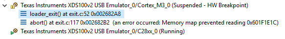
After looking into it it seems this error occurs with BIOS_start().
I tried to manipulate the memory in the beginning of main with the following code and it doesn't raise any error:
short *MemLoc = (short *)(0x601F1E1C);
*MemLoc = 1234;
To summarize, accessing the external SRAM works fine with other sections than .bss, and EPI is initialized with XDC reset and startup functions so supposedly before .bss initialization with zeros.
Could you please tell me if I missed a step in EPI initialization, which would make the BIOS_start() fail ?
Thank you in advance for your help.
Yours Sincerely,
Paul Noalhyt


