This thread has been locked.

If you have a related question, please click the "Ask a related question" button in the top right corner. The newly created question will be automatically linked to this question.

CCS/TMS320F28035: Peak Current Mode Control Buck Converter

Part Number: TMS320F28035
Other Parts Discussed in Thread: CONTROLSUITE

Tool/software: Code Composer Studio

Dear C2000 experts,

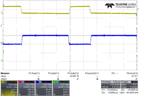
I'm using the F28035 to develop a buck converter with the synchronous rectifier and there is a dead time between the MOS switches. The topology I choose is the Hard-Switching Full-Bridege and the control method is the peak current mode control. I can generate the 1st side MOS control with the TZ function with the comparator, but cannot get the correct waveform of 2nd side SR MOS.    The figure below is the waveform I would like to generate. The yellow one is the 1st side waveform and the blue one is the SR waveform.

Is there any sample code that I can refer?

Many thanks for the help.

Young

  • Young,

    You can take a look at some of the support files from the HVPSFB kit in controlSUITE.  The F2802x code there should be fully compatible with F2803x.

    \ti\controlSUITE\development_kits\HVPSFB_v1.1\

    I think that you will want to look into the EPWM Dead-Band Submodule to generate complementary waveforms with dead time.

    -Tommy

  • Tommy,

    Thanks for the reply.

    I have traced the code of the sample code you mention and compared with the provided user note recently. But during the process, I encounter some problem.

    In the function of PWM_PSFB_PCMC_Cnf.C :

    Section of PWM2 (*ePWM[n+1]) control:

    Q1. Why the PWM2A can be trigger due to the CMPA is set at the counter equals to period+10 which would not reach?

    Section of cyle-by-cycle sutdown mechanism of PWM2

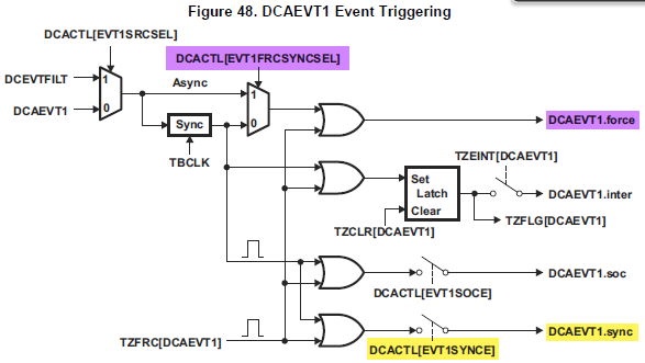
    Q2. Why the EVT1SYNCE can be used when the path is chosen as the DC_EVT_ASYNC path?

    According to the block diagram from ePWM note, the EVT1SYNCE can be used when the path is chosen the sync path.

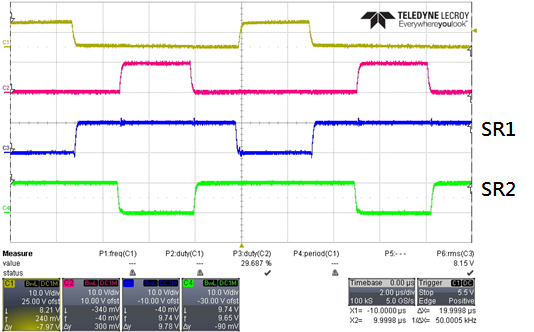
    We would like to generate two pairs of waveform which are similar to PWM2 A/B but these two pairs would be shift with 180 degree. (As the figure below)

    The topology we choose is Full bridge hard switch with peak current mode control method.


    thanks,

    Young

  • Young (CY) Chen said:
    Q1. Why the PWM2A can be trigger due to the CMPA is set at the counter equals to period+10 which would not reach?

    Section of cyle-by-cycle sutdown mechanism of PWM2

    This is just a starting value to put the pins in a known state until ePWM1 generates an interrupt.  The CMPA values are updated inside of the interrupt handler in HVPSFB-DPL-ISR.asm once the system is running.

    Young (CY) Chen said:
    Q2. Why the EVT1SYNCE can be used when the path is chosen as the DC_EVT_ASYNC path?

    According to the block diagram from ePWM note, the EVT1SYNCE can be used when the path is chosen the sync path.

    From the ePWM Reference Guide, these are separate paths to different endpoints:

    Young (CY) Chen said:
    We would like to generate two pairs of waveform which are similar to PWM2 A/B but these two pairs would be shift with 180 degree. (As the figure below)

    The topology we choose is Full bridge hard switch with peak current mode control method.


    As an example, the VMC solution uses TBPHS to vary the phase between ePWM1 and ePWM2.  180 degrees is certainly possible.

    If your signal pairs (Yellow+Red vs Blue+Green) will always be synchronously complementary as shown, the output can probably be achieved by setting complementary AQCTL and trip behaviors while keeping the two ePWMs in the same phase.

  • Q1.

    But inside the DPL-ISR, the CMPA or B of EPWM2 are still set as PWM_PRD+10, I was wondering if it is possible to let the counter larger than the period?

    Q2.

    Due to the setting of Cycle-by-Cycle of the PWM inside the PWM_PSFB_PCMC_Cnf.C sub-function is chosen the path of async. one, which means the yellow highlighted one will not occur unless the TZFRC is used (But I don't see this inside the code.).

    Q3.

    Our signal pairs are indeed complementary, but will have a certain dead time between rising or falling edge. However, the control method we  would like to apply is the peak current mode instead of the VMC, which means the response must be fast enough to check the current condition. That why it might need to use the comparator function to realize. But there's no any sample code is similar to our condition. The PWM behaviors of PSFB are not look like our expected one. The waveform of its PWMs are much more complicated than ours.

    Thanks for the help!

    Young  

  • Young,

    Q1: The 'PRD+10' is intentional and is part of the code to achieve hardware based dead-band between high-side and low-side switches after the peak current event. This is done to make sure a wrong action qualifier (AQ) action does not take place in the wrong half-cycle of the switching period.

    Q2: TZFRC is not used. The trip/shut-down of the PWM is completely in the hardware. Because of the phase shifted full bridge topology there is some time-critical software run inside the ISR to make sure the correct PWM output (high-side/low-side) is tripped in each half of the switching cycle. The other PWM output (low-side/high-side) is turned ON after a dead-time. This dead-time is in hardware but made possible by the rewriting of the CMP registers in the ISR.

    Q3: The HVPSFB implementation uses the on-chip comparator and the async trip behavior to provide the best possible response. This is true analog peak current mode control implementation with a digital controller.

    On newer devices (F28004x, F2807x) with type-4 PWMs there is an easier way to implement this. Please refer to the post below


    I hope this helps.

    Hrishi

  • Young,

    It has been over a week since your last update. I assume that you were able to resolve your issue. If this isn’t the case, please reject this resolution and reply to this thread. If this thread is locked, please make a new thread describing the current status of your issue.

    -Tommy