Tool/software: Code Composer Studio
Hi everyone, this is Mike,
I have an issue with the ecap module and the gpio interrupts.
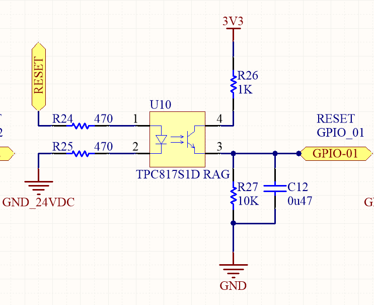
I'm currently using the ecap 1 (GPIO5 ) and the external interrupts (GPIO0 and GPIO1) when I press the button, doing the gpio interrupt, it seems the Timerstamp counter freezes and gives me errors in my measurements ( I'm measuring frequency with the ecap)
So, is there any kind of missing interrupt or something? Just this thing appears when I press the buttons.
Here it is the settings of both interrups, and, of course, its routine into the interrupt function.
void freq_settings(void)
{
    EALLOW;                                     //Emulación de registros
    SysCtrlRegs.PCLKCR1.bit.ECAP1ENCLK = 1;     // SYSCLKOUT para habilitar eCAP1
    /************ Se inicia el módulo ECAP para medir el periodo y el ancho de pulso de una señal.**********/
    ECap1Regs.ECEINT.all = 0;                   // Deshabilita todas las interrupciones del módulo eCAP
    ECap1Regs.ECCTL1.bit.CAPLDEN = 0;           // Deshabilita la carga de los resultados de captura
    ECap1Regs.ECCTL2.bit.TSCTRSTOP = 0;         // Detiene el contador
    ECap1Regs.TSCTR = 0;                        // Limpia el contador
    ECap1Regs.CTRPHS = 0;                       // Limpia el registro de contador de fase
    ECap1Regs.ECCTL2.bit.CAP_APWM = 0;          // Modo Captura
    ECap1Regs.ECCTL2.bit.SWSYNC = 0;            // Sincronización forzada Deshabilitada
    ECap1Regs.ECCTL2.bit.SYNCO_SEL = 10;        // Syncin = Syncout, requerido por SWSYNC
    ECap1Regs.ECCTL2.bit.SYNCI_EN = 0 ;          // Habilita sincronización de entrada
    ECap1Regs.ECCTL2.bit.TSCTRSTOP = 1;         // Time Stamp Counter free-running
    ECap1Regs.ECCTL2.bit.REARM = 0;             // No Re-arme (Re-arme ->arma una secuencia de captura predeterminada)
    ECap1Regs.ECCTL2.bit.STOP_WRAP = 11;        // Toma 4 capturas en modo continuo
    ECap1Regs.ECCTL2.bit.CONT_ONESHT = 0;       // Operando en modo continuo
    ECap1Regs.ECCTL1.bit.FREE_SOFT= 11;         // Time Stamp Counter no es afectado por le emulación suspendida
    ECap1Regs.ECCTL1.bit.PRESCALE = 00000;      // Dividido entre 1
    ECap1Regs.ECCTL1.bit.CAPLDEN = 1;           // Habilita los registros de carga CAP1-4 en un evento
    ECap1Regs.ECCTL1.bit.CTRRST4 = 0;           // Sin reset en la primera captura
    ECap1Regs.ECCTL1.bit.CAP4POL = 1;           // Captura en el ascenso de la señal
    ECap1Regs.ECCTL1.bit.CTRRST3 = 0;           // Sin reset en la segunda captura
    ECap1Regs.ECCTL1.bit.CAP3POL = 0;           // Captura en el descenso de la señal
    ECap1Regs.ECCTL1.bit.CTRRST2 = 0;           // Sin reset en la tercera captura
    ECap1Regs.ECCTL1.bit.CAP2POL = 1;           // Captura en el ascenso de la señal
    ECap1Regs.ECCTL1.bit.CTRRST1 = 0;           // Sin reset en la cuarta captura
    ECap1Regs.ECCTL1.bit.CAP1POL = 0;           // Captura en el descenso de la señal
    /****************************************************************************************************/

    /************ Interrupciones del ECAP ****************/
    PieVectTable.ECAP1_INT = &freq_isr;          // El contenido del subprograma de interrupción "ecap_isr" es copiado por el subprograma de interrupción "ECAP1_INT" contenido en la tabla.
    ECap1Regs.ECEINT.all = 0x0008;              // Habilita las interrupciones
    PieCtrlRegs.PIEIER4.bit.INTx1 = 1;          // Habilita la interrupción de ECAP1_INT en PIE grupo 4
    IER |= 0x0008;                              // Habilita INT4 en IER para habilitar el grupo 4 del bloque de interrupciones
    EINT;
    ERTM;
    /******************************************************/

    /*********** Configuración del pin de entrada para el ECAP *********/
     GpioCtrlRegs.GPACTRL.all  = 0x00000000;
     GpioCtrlRegs.GPAMUX1.bit.GPIO5 = 3;        // GPIO 5 Configurado para captura de pulsos
     GpioCtrlRegs.GPADIR.bit.GPIO5 = 0;         // GPIO 5 como entrada
     //GpioCtrlRegs.GPAPUD.bit.GPIO5 = 0;         // Pull-up habilitado para GPIO5 (0)
    /* GpioCtrlRegs.GPAMUX2.bit.GPIO24 = 1;        // GPIO 5 Configurado para captura de pulsos
     GpioCtrlRegs.GPADIR.bit.GPIO24 = 0;         // GPIO 5 como entrada
     GpioCtrlRegs.GPAPUD.bit.GPIO24 = 0;         // Pull-up habilitado para GPIO5 (0)*/
    /*****************************************************************/
     EDIS;                            // Deshabilita la emulación de registros
}

void reset_stop_inhibit_settings(void)
{
    EALLOW;
    PieVectTable.XINT1 = &reset_isr;    // El contenido del subprograma de interrupción "reset_isr" es copiado por el subprograma de interrupción "XINT1" contenido en la tabla.
    PieVectTable.XINT2 = &emergency_stop_isr; // El contenido del subprograma de interrupción "emergency_stop_isr" es copiado por el subprograma de interrupción "XINT2" contenido en la tabla.
    PieVectTable.XINT3 = &inhibit_isr;  // El contenido del subprograma de interrupción "inhibit_isr" es copiado por el subprograma de interrupción "XINT3" contenido en la tabla.
    PieCtrlRegs.PIECTRL.bit.ENPIE = 1;  // Habilita el bloque de Puerto Expandido de Interrupciones
    PieCtrlRegs.PIEIER1.bit.INTx4 = 1;  // Habilita el PIE grupo 1 INT 4 para XINT1, consultar spruh18g.pdf pag 176-177
    PieCtrlRegs.PIEIER1.bit.INTx5 = 1;  // Habilita el PIE grupo 1 INT 1 para XINT5, consultar spruh18g.pdf pag 176-177
    //PieCtrlRegs.PIEIER12.bit.INTx1 = 1; // Habilita el PIE grupo 12 INT 1 para XINT3, consultar spruh18g.pdf pag 176-177
    IER |= M_INT1;                      // Habilita interrupciones del CPU 1
    //IER |= M_INT12;                     // Habilita interrupciones del CPU 12
    EINT;                               // Habilita interrupciones globales
    EDIS;
    EALLOW;
    /* STOP */
    GpioCtrlRegs.GPAMUX1.bit.GPIO0 = 0;  // GPIO0 como Digital I/O, no funciones especiales
   //GpioDataRegs.GPACLEAR.bit.GPIO0 = 1; // Limpia registro GPIO0
    GpioCtrlRegs.GPADIR.bit.GPIO0 = 0;   // GPIO0 como entrada
    GpioCtrlRegs.GPAQSEL1.bit.GPIO0 = 0; // XINT1 sincronizado al reloj del sistema solamente

    /* RESET */
    GpioCtrlRegs.GPAMUX1.bit.GPIO1 = 0;  // GPIO1 como Digital I/O, no funciones especiales
    //GpioDataRegs.GPACLEAR.bit.GPIO1 = 1; // Limpia registro GPIO01
    GpioCtrlRegs.GPADIR.bit.GPIO1 = 0;   // GPIO01 como entrada
    GpioCtrlRegs.GPAQSEL1.bit.GPIO1 = 0;        // XINT2 Qual usa 6 muestras
    //GpioCtrlRegs.GPACTRL.bit.QUALPRD0 = 0xFF;   // Cada ventana de muestreo es 510 veces el reloj del sistema (510*SYSCLKOUT)
       // INHIBIT
    //GpioCtrlRegs.GPBMUX1.bit.GPIO32 = 0;  // GPIO32 como Digital I/O, no funciones especiales
    //GpioDataRegs.GPBCLEAR.bit.GPIO32 = 1; // Limpia registro GPIO32
    //GpioCtrlRegs.GPBDIR.bit.GPIO32 = 1;   // GPIO32 como entrada
    //GpioCtrlRegs.GPAQSEL2.bit.GPIO32 = 0; // XINT1 sincronizado al reloj del sistema solamente
    EDIS;

    // GPIO0 es XINT1, GPIO1 es XINT2
    EALLOW;
    GpioIntRegs.GPIOXINT1SEL.bit.GPIOSEL = 0;   // XINT1 es GPIO0 (STOP)
    GpioIntRegs.GPIOXINT2SEL.bit.GPIOSEL = 1;   // XINT2 es GPIO1 (RESET)
    //GpioIntRegs.GPIOXINT3SEL.bit.GPIOSEL = 32;  // XINT3 is GPIO1 (INHIBIT)

    // Configuración de XINT1 y XINT2
    XIntruptRegs.XINT1CR.bit.POLARITY = 1;      // Interrupción en el flanco positivo
    XIntruptRegs.XINT2CR.bit.POLARITY = 1;      // Interrupción en el flanco negativo
    //XIntruptRegs.XINT3CR.bit.POLARITY = 1;    // Interrupción en el flanco positivo

    // Habilitar XINT1 y XINT2
    XIntruptRegs.XINT1CR.bit.ENABLE = 1;        // Habilita XINT1
    XIntruptRegs.XINT2CR.bit.ENABLE = 1;        // Habilita XINT2
    // XIntruptRegs.XINT3CR.bit.ENABLE = 1;     // Habilita XINT3
    EDIS;

}

__interrupt void
freq_isr(void)
{

    // Calcula el ciclo de trabajo (flanco ascendente a flanco descendente)
    //   PwmDuty = (int32)ECap1Regs.CAP2 - (int32)ECap1Regs.CAP1;
    // Calcula el periodo  (flanco ascendente a flanco ascendente)
    PwmPeriod = (int32)ECap1Regs.CAP3 - (int32)ECap1Regs.CAP1;
    Periodo = (PwmPeriod/90401640.0);
    Frecuencia = 1/Periodo;
    ECap1Regs.ECCLR.bit.CEVT3 = 1;              // Limpia la bandera de CEVT3
    ECap1Regs.ECCLR.bit.INT = 1;                // Limpia l bandera de interrupción de ECAP1
    PieCtrlRegs.PIEACK.all = PIEACK_GROUP4;     // Debe reconocer el grupo PIE
}


__interrupt void reset_isr(void)
{

     if(flag_emergency_break_on == TRUE)
    {
        flag_emergency_break_on = FALSE;
    }

    PieCtrlRegs.PIEACK.all = PIEACK_GROUP1;
    }

__interrupt void emergency_stop_isr(void)
{
    flag_emergency_break_on = TRUE;
    PieCtrlRegs.PIEACK.all = PIEACK_GROUP1;
 }


