This thread has been locked.

If you have a related question, please click the "Ask a related question" button in the top right corner. The newly created question will be automatically linked to this question.

CCS/LAUNCHXL-F28379D: How can i generate this signal?

Part Number: LAUNCHXL-F28379D
Other Parts Discussed in Thread: C2000WARE

Tool/software: Code Composer Studio

Hello,

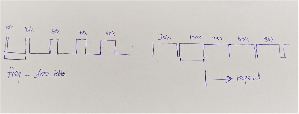
I wanna generate the following signal using LAUNCHXL-F28379D. Is there a way to configure ePWM to change the duty cycle in each period (like 10%, 20%, ...., 90%, 100% and then 100%, 90%,....., 10%) and then repeat the process again and again?

Regards,

Younes

  • Just received your question Younes. I am working on it.

  • The ePWM module can definitely generate this. Take a look at the slider examples that we have in C2000WARE. Specifically,

    dev.ti.com/.../
    dev.ti.com/.../

    These examples can be found in resource explorer.
  • I used the example you provided me and the ISR worked fine but  the dutycycle doesn't change tho because of updown count. So i tried to change the count mode to UP but the code doesn't enter ISR at all, what did i do wrong !?

    //
    // Included Files
    //
    #include "F28x_Project.h"
    
    //
    // Defines
    //
    #define EPWM1_TIMER_TBPRD  2000  // Period register
    
    
    //
    // Function Prototypes
    //
    void InitEPwm1Example(void);
    __interrupt void epwm1_isr(void);
    
    
    int i = 1;
    //
    // Main
    //
    void main(void)
    {
    //
    // Step 1. Initialize System Control:
    // PLL, WatchDog, enable Peripheral Clocks
    // This example function is found in the F2837xD_SysCtrl.c file.
    //
        InitSysCtrl();
    
    //
    // Step 2. Initialize GPIO:
    // This example function is found in the F2837xD_Gpio.c file and
    // illustrates how to set the GPIO to it's default state.
    //
    //    InitGpio();
    
    //
    // enable PWM1, PWM2 and PWM3
    //
        CpuSysRegs.PCLKCR2.bit.EPWM1=1;
    
    //
    // For this case just init GPIO pins for ePWM1, ePWM2, ePWM3
    // These functions are in the F2837xD_EPwm.c file
    //
        InitEPwm1Gpio();
    
    //
    // Step 3. Clear all interrupts and initialize PIE vector table:
    // Disable CPU interrupts
    //
        DINT;
    
    //
    // Initialize the PIE control registers to their default state.
    // The default state is all PIE interrupts disabled and flags
    // are cleared.
    // This function is found in the F2837xD_PieCtrl.c file.
    //
        InitPieCtrl();
    
    //
    // Disable CPU interrupts and clear all CPU interrupt flags:
    //
        IER = 0x0000;
        IFR = 0x0000;
    
    //
    // Initialize the PIE vector table with pointers to the shell Interrupt
    // Service Routines (ISR).
    // This will populate the entire table, even if the interrupt
    // is not used in this example.  This is useful for debug purposes.
    // The shell ISR routines are found in F2837xD_DefaultIsr.c.
    // This function is found in F2837xD_PieVect.c.
    //
        InitPieVectTable();
    
    //
    // Interrupts that are used in this example are re-mapped to
    // ISR functions found within this file.
    //
        EALLOW; // This is needed to write to EALLOW protected registers
        PieVectTable.EPWM1_INT = &epwm1_isr;
        EDIS;   // This is needed to disable write to EALLOW protected registers
    
    //
    // For this example, only initialize the ePWM
    //
        EALLOW;
        CpuSysRegs.PCLKCR0.bit.TBCLKSYNC = 0;
        EDIS;
    
        InitEPwm1Example();
    
        EALLOW;
        CpuSysRegs.PCLKCR0.bit.TBCLKSYNC = 1;
        EDIS;
    
    //
    // Step 4. User specific code, enable interrupts:
    //
    
    //
    // Enable CPU INT3 which is connected to EPWM1-3 INT:
    //
        IER |= M_INT1;
    
    //
    // Enable EPWM INTn in the PIE: Group 3 interrupt 1-3
    //
        PieCtrlRegs.PIEIER1.bit.INTx1 = 1;
    
    //
    // Enable global Interrupts and higher priority real-time debug events:
    //
        EINT;  // Enable Global interrupt INTM
        ERTM;  // Enable Global realtime interrupt DBGM
    
    //
    // Step 5. IDLE loop. Just sit and loop forever (optional):
    //
        for(;;)
        {
            asm ("    NOP");
        }
    }
    
    //
    // epwm1_isr - EPWM1 ISR
    //
    __interrupt void epwm1_isr(void)
    {
    
    
        EPwm1Regs.CMPA.bit.CMPA = (EPWM1_TIMER_TBPRD/10)*i;    // Set compare A value
        EPwm1Regs.CMPB.bit.CMPB = (EPWM1_TIMER_TBPRD/10)*i;    // Set Compare B value
        i++;
        if( i == 11){i = 1;}
    
        //
        // Clear INT flag for this timer
        //
        EPwm1Regs.ETCLR.bit.INT = 1;
    
        //
        // Acknowledge this interrupt to receive more interrupts from group 3
        //
        PieCtrlRegs.PIEACK.all = PIEACK_GROUP1;
    }
    
    //
    // InitEPwm1Example - Initialize EPWM1 configuration
    //
    void InitEPwm1Example()
    {
        //
        // Setup TBCLK
        //
        EPwm1Regs.TBPRD = EPWM1_TIMER_TBPRD;       // Set timer period 801 TBCLKs
        EPwm1Regs.TBPHS.bit.TBPHS = 0x0000;        // Phase is 0
        EPwm1Regs.TBCTR = 0x0000;                  // Clear counter
    
        //
        // Set Compare values
        //
        EPwm1Regs.CMPA.bit.CMPA = EPWM1_TIMER_TBPRD/2;    // Set compare A value
        EPwm1Regs.CMPB.bit.CMPB = EPWM1_TIMER_TBPRD/2;    // Set Compare B value
    
        //
        // Setup counter mode
        //
        EPwm1Regs.TBCTL.bit.CTRMODE = TB_COUNT_UP; // Count up and down
        EPwm1Regs.TBCTL.bit.PHSEN = TB_DISABLE;        // Disable phase loading
        EPwm1Regs.TBCTL.bit.HSPCLKDIV = TB_DIV1;       // Clock ratio to SYSCLKOUT
        EPwm1Regs.TBCTL.bit.CLKDIV = TB_DIV1;
    
        //
        // Setup shadowing
        //
    
        EPwm1Regs.CMPCTL.bit.SHDWAMODE = CC_SHADOW;
        EPwm1Regs.CMPCTL.bit.SHDWBMODE = CC_SHADOW;
        EPwm1Regs.CMPCTL.bit.LOADAMODE = CC_CTR_ZERO; // Load on Zero
        EPwm1Regs.CMPCTL.bit.LOADBMODE = CC_CTR_ZERO;
    
        //
        // Set actions
        //
        EPwm1Regs.AQCTLA.bit.ZRO = AQ_SET;            // Set PWM1A on event A, up
        EPwm1Regs.AQCTLA.bit.CAU = AQ_CLEAR;                                       // count
        //EPwm1Regs.AQCTLA.bit.PRD = AQ_SET;          // Clear PWM1A on event A,
        //EPwm1Regs.AQCTLA.bit.CAD = AQ_CLEAR;
    
        //EPwm1Regs.AQCTLA.bit.CAU = 1;                            // down count
    
        ////B
        EPwm1Regs.AQCTLB.bit.ZRO = AQ_SET;            // Set PWM1A on event A, up
        EPwm1Regs.AQCTLA.bit.CBU = AQ_CLEAR;                               // count
        //EPwm1Regs.AQCTLB.bit.PRD = AQ_SET;          // Clear PWM1A on event A,
        //EPwm1Regs.AQCTLA.bit.CBD = AQ_CLEAR;
    
    
        //
        // Interrupt where we will change the Compare Values
        //
        EPwm1Regs.ETSEL.bit.INTSEL = 1;                      //        ET_CTR_ZERO;     // Select INT on Zero event
        EPwm1Regs.ETSEL.bit.INTEN = 1;                // Enable INT
        EPwm1Regs.ETPS.bit.INTPRD = ET_1ST;           // Generate INT on 3rd event
    
    }
    
    //
    // End of file
    //
    

    I don't know what's wrong with this code!? is it (EPwm1Regs.ETSEL.bit.INTSEL = 1; //2 3 4 5) because i tried all possibilities ?


  • Please ACK the correct group in the ISR.

        //
        // Acknowledge this interrupt to receive more interrupts from group 3
        //
        PieCtrlRegs.PIEACK.all = PIEACK_GROUP3;

    You are ACKING GROUP 1.  

  • Also enable the correct ACK group.

    PIEIER3 not IER1
  • Thanks,
    when i used PIE Group 3, code works fine.
    i understand from your answer that epwm interrupt works only with group 3 !!