This thread has been locked.

If you have a related question, please click the "Ask a related question" button in the top right corner. The newly created question will be automatically linked to this question.

TMS320F280049: C2000™ microcontrollers forum

Part Number: TMS320F280049
Other Parts Discussed in Thread: LAUNCHXL-F280049C

The prototype of F280049 used by customer is in the process of debugging. At present, there are some problems in the use of internal 1.2V dc-dc module. I need your help to answer them.
During the test, they found that the PWM waveform in GPIO_23VSW output is not continuous, and it is intermittent, resulting in a large ripple in the voltage of output capacitor. The recommended parameters are selected for the external inductance and capacitance.
Is it normal to have intermittent phenomenon? Or is it caused by incorrect configuration of software and hardware? Thank you!
The following is the related hardware and software configuration and waveform for reference.

Software configuration:
Void InItDCDC (void)
{
    EALLOW;
    AnalogSubsysRegs.DCDCCTL.bit.DCDCEN=1;
    While ((AnalogSubsysRegs.DCDCSTS.Bit.INDDETECT! = 1) ||(AnalogSubsysRegs.DCDCSTS.Bit.SWSEQDONE! = 1))
    {/ / waiting to be set
    }
    EDIS;
    DELAY_US(80); / / delay 80us
}
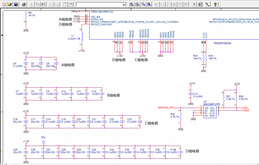
The schematic diagram of this part of our company is as follows:

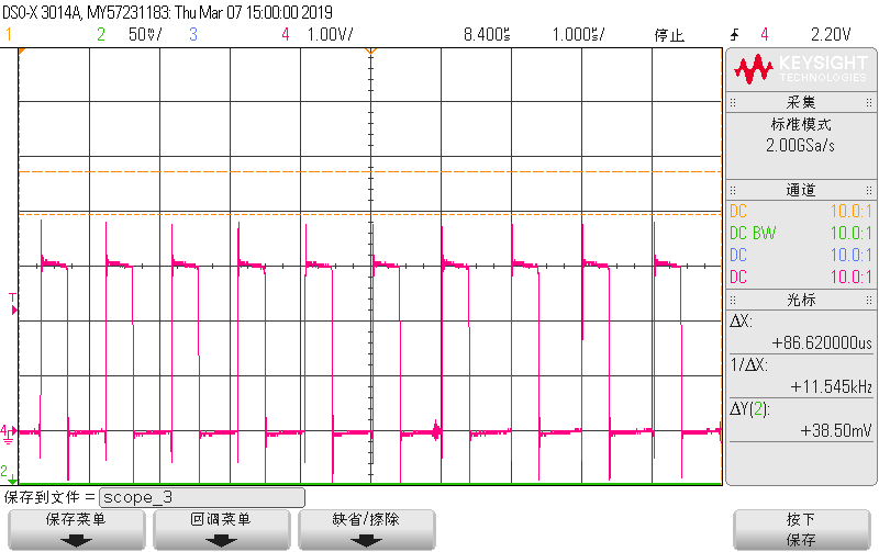
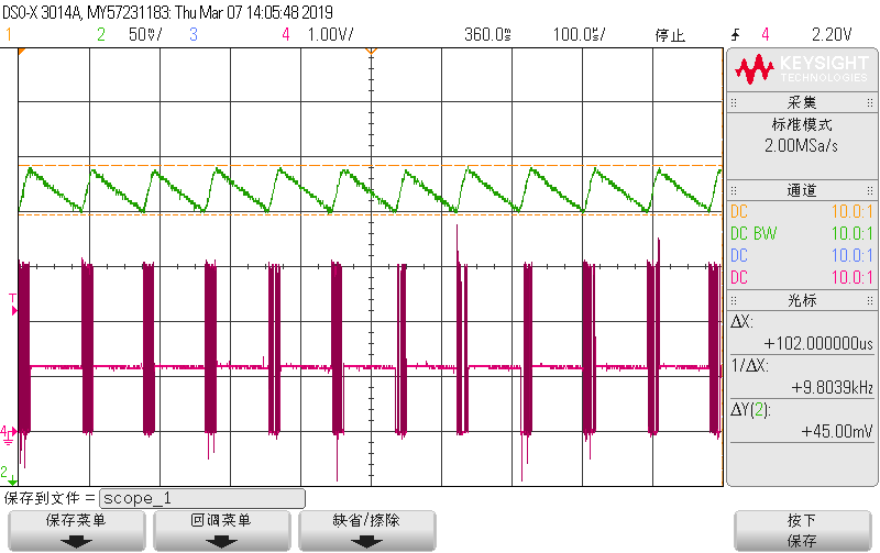
The figure below shows the output of GPIO23_VSW and 1.2V waveform detected by our oscilloscope, in which the red waveform is the output of GPIO23_VSW and the green is 1.2V.

The figure below shows the output of GPIO23_VSW with pulse after expansion.

  • Hi Qun,

    What they are seeing is normal. The DCDC is operating in discontinuous conduction mode where the current through the inductor will drop to zero before the cycle ends.

    I will however mention that their total capacitance is exceeding our specification. If i am reading your schematic correctly, the total bulk capacitance they have on 1.2v rail is 110uF and on the 3.3v rail, over 70uF. These capacitances are well above the requirements in the datasheet which is 20uF each. Please tell them to follow the datasheet requirements.

  • Hi, Frank

    The customer will modify the capacitors' value to test tomorrow. But yesterday I told them the inductor is in discontinuous conduction and ask them increase the value of inductor or increase the load current. They did tests and found the inductor has increased to 16uH which is no use to wave, but paralleling a 5Ω in 1.2V rail for simulating load current increase made the PWM wave continuous .

    What does this mean?

  • And the customer said LAUNCHXL-F280049C EVM had the similar phenomenon , is it convenient for you to test the EVM board to see what wave it is?

    Regards 

    Qun

  • Qun,

    Yes, that is also expected. The DCDC will switch to continuous conduction mode when the current draw exceeds a specified level which is why they are seeing the DCDC output smooth out when the 5ohm load is placed on it. However, they shouldn't do this. The DCDC was designed to sufficiently power the F28004x device only and nothing more. A 5ohm load places an additional 240mA load on the DCDC. If the DCDC current limit is exceeded, it will shut-off and the device will crash. For normal device current operation, the DCDC will not switch to continuous conduction mode. This is by design so everything they are seeing is normal.

    Also, please tell them not to use a 16uH inductor, they should follow the requirements we have in the datasheet.