This thread has been locked.

If you have a related question, please click the "Ask a related question" button in the top right corner. The newly created question will be automatically linked to this question.

what do I need to pay attention to,if I use the hall sensor to sample phase current?

Other Parts Discussed in Thread: DRV8301-69M-KIT, DRV8301, OPA365, CONTROLSUITE, MOTORWARE

I want to design my board with InstaSPIN motion technology

Rated current:400A

Rated voltage:48V

Speed of motor(BLDC):4000-5000 RPM

I have bought Drv8301-69M-kit (60V 40A),I think I can a little changes on this kit.E.g.replace MOSFET and current sensor etc.

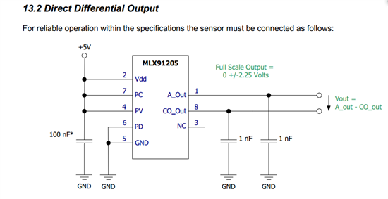
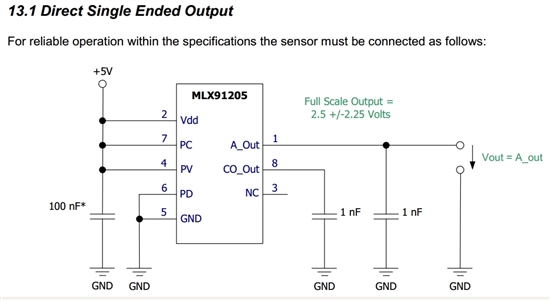
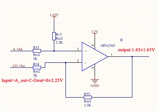
So,I use the hall sensor(MLX91205) to sample phase current. but the output of MLX91205 sensor is differential and Full Scale Output = 0 +/-2.25 Volts.

As below:

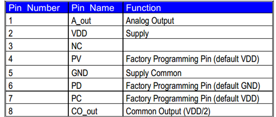
I found the CO_Out PIN don't connect GND,which equals VDD/2 in datasheet,while SP1 PIN of Drv8301 connect GND:


I am in doubt:

1.Can I connect CO_Out PIN to SP1 PIN of Drv8301 and connect ?

2.Is full scale output of MLX91205 sensor appropriate for current shunt amplifier of Drv8301?

3.Otherwise is there anything else I should do about the high current circuit?

I'm sorry to trouble engineers.

  • Now I found a new problem: the position of sample current with hall sensor is different from  Drv8301 kit.

    As a result,the direction of  current is different.

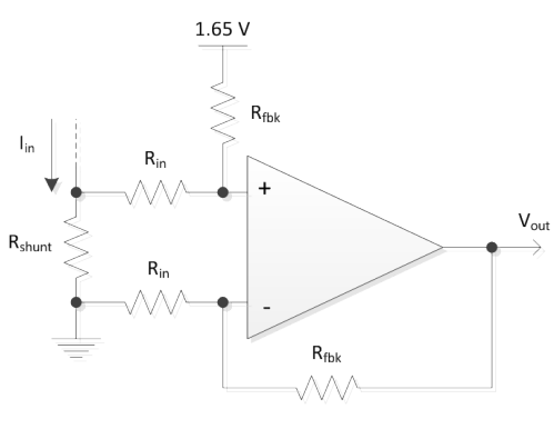
    TI's method,the shunt resistor is placed in the bottom of mosfet,so the direction of  current is unidirectional:

    While use hall sensor,the direction of  current is bidirectional.

    I think it will bring some mistakes,but I have to use hall sensor in the high current circuit application.

    what can I do?

  • Hi Chao,

    I am not to familiar with this device but will try and provide some insight.

    If the amplifier has +/-2.25V output then you should not be connecting it to the amplifier of the DRV8301. It has already been amplified.

    I think that you are going to run into some issues since this is a 5V part and the C2000 is a 3.3V part.

    Low-side MOSFET shunt resistor sense is indeed bidirectional. You will see that it is biased at 1.65V.  Current can flow in reverse when recirculating in the motor winding. We prefer this method since you are placing the resistance in line with the GND side (0V potential) of the half-bridge.

    How are you planning on placing this sensor on the DRV8301 board? I would recommend evaluating our method on our EVM first, testing the sensor standalone, and then creating your own hardware. We often see people do high current sensing (>100A) with shunt resistors but you must size appropriately.

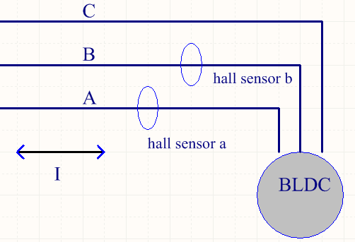
  • you can use magnetic hall current sensors for in-line phase currents no problem.

    what you need to do is to provide a bi-directional, scaled value of this to the ADC pin.

    0 V @ ADC Pin = -2.5V from current sensor = maximum negative A

    1.65 V @ ADC Pin = 0V from current sensor = 0 A

    3.3 V @ ADC Pin = +2.5V from current sensor = maximum positive A


    You should go ahead and convert your 5V range to a 3.3V range centered at 1.65.


  • Thanks.

    Look J6 with DAC1\2\3\4 in the  Schematic of DRV8301 KIT,What use is it? For DAC test?

    It looks like an external interface.Can I delete it in my own circuit design?

  • Correct, option for DAC signals during debug. Not critical to the control system.


  • Hello Nicholas Oborny

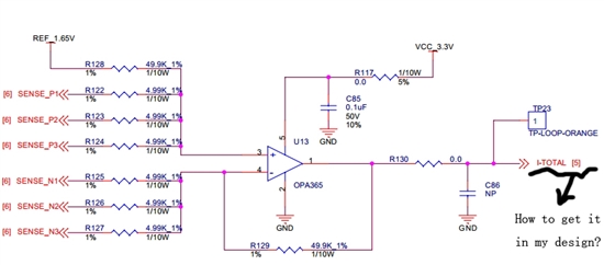
    I do My own design and have a new problems: How to design circuit to get DC bus current I-TOTAL?

    Look at my current detection circuit:

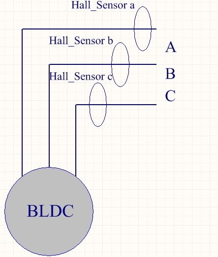
    1.I detect phase current with hall sensor(MLX91205) :

    2.I design circuit according to the manual:

    3.I convert analog voltage:

    But I finally found I cannot get DC bus current (the I-TOTAL signal of DRV8301 kit)  in this way. Could you give me some advice?

  • Chris may be able to better comment here.

    In this circuit, the DC bus current is simply the sum of the 3 half-bridges. One option, you could place a sensor in the ground path where the 3 half bridges merge, but before they connect to the remaining board ground. You could also do high side sense in the supply line for the 3 half-bridges.

  • Nicholas Oborny said:
    One option, you could place a sensor in the ground path where the 3 half bridges merge, but before they connect to the remaining board ground.

    This is what we would typically do. 

  • Hi Chris,I met some trouble in the design of hardware.

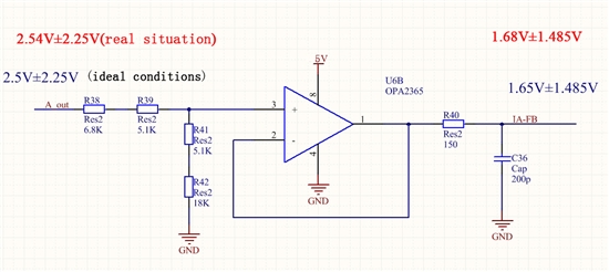
    1. A_out PIN of MLX91205 is 5V/2±2.25V under ideal conditions,but the power supply which is generated by DRV8301chip was not exactly equal to 5V.It was 5.08V.So A_out PIN of MLX91205 became 5.08V/2±2.25V,if phase current value is equal to zero,then I wil get 1.68V,not 1.65V.

    I think the error will affect motor control,therefore I have to use differential output(A_out and CO_out) form of MLX91205 and 3.3V.Because differential output voltage range is 0 ± 2.25V,I have to create an attenuator.

    But,iit feasible that change opa365 into attenuator? I fear that it generates self - oscillation or other problems

    Is there a better way to do this,if you think my idea is not good?

    2.I have saw the schematic of DRV8301 kit.These are three OPAMPs(TLV2781DBVR) for three-phase current measurement.I think it is enough.So I do not understand what the two current amplifiers of DRV8301 are used for?

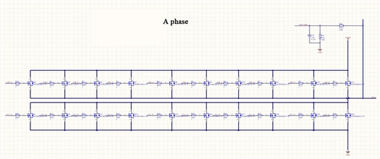
    3.My circuit board works on low-voltage and high-current occasion,so some MOSFETs are used in parallel combination,I want to know how many MOSFET DRV8301 can drive? 

  • you can review our HW schematics for how we recommend doing the current sense. It should be like this (with your own values of R for your scaling):

  • I have seen HW schematics before.In my application,the phase current of my motor is 300A-400A.The current  is too large,so there is no suitable resistor.

    I have to make hall sensor(MLX91205) detect phase current.6644.MLX91205_datasheet.pdf

    So,I encounter above mentioned three problems and need your advice.


  • If you use hall type sensors to measure motor currents there is no difference in the code as long as the end voltage is center around 1.65V and the total swing stays withing 0.0V to 3.3V (ADC voltage). Even if the reference voltage is not perfectly 1.65 (in example 1.68) the small difference is calculated as an offset in software so don't worry about this small difference of 0.03 V.

    As far as how to calculate I_TOTAL, it depends what you have. If you have the three currents coming from hall type current sensors (non differential), then do a summer OPAMP (look for "Summing amplifier"): http://en.wikipedia.org/wiki/Operational_amplifier_applications

    Please summarize the open questions at this point so I can help.

    -Jorge


  •  I appreciate Jorge's help.I think you have helped me solve question 1.

    But I have some doubts about the above question 2(I have saw the schematic of DRV8301 kit.These are three OPAMPs(TLV2781DBVR) for three-phase current measurement.I think it is enough.So I do not understand what the two current amplifiers of DRV8301 are used for?) and question 3(My circuit board works on low-voltage and high-current occasion,so some MOSFETs are used in parallel combination,I want to know how many MOSFET DRV8301 can drive?)

    I have used AUIRFS4010-7P.This is the datasheet of this MOSFET.

    7282.MOSFET_datasheet.pdf

  • chao yang said:
    question 2(I have saw the schematic of DRV8301 kit.These are three OPAMPs(TLV2781DBVR) for three-phase current measurement.I think it is enough.So I do not understand what the two current amplifiers of DRV8301 are used for?)

    In the controlSUITE SW we use the two on-DRV8301 PGAs for current sense amplification. For MotorWare / InstaSPIN-FOC/-MOTION we use the three external so we can show over-modulation.

    chao yang said:
    question 3(My circuit board works on low-voltage and high-current occasion,so some MOSFETs are used in parallel combination,I want to know how many MOSFET DRV8301 can drive?)

    I've seen several boards that do this with DRV8301, but it's out of my expertise.  I know the guys on the Motor Drive e2e forum can help with this question.

    http://e2e.ti.com/support/applications/motor_drivers/default.aspx


  • Hi Chao,

    The DRV8301 has a total average gate drive current of 30mA. The Qg of the FET and switching frequency of your system will approximately determine the FET and # of them you can drive.

    t ~= Q / Idrive